Specifications
| Type | Rotary potentiometer on a voltage divider, analog output |
|---|---|
| Potentiometer | 10 kΩ linear (B10K), RV09 style, standing on the top edge with a Ø6 mm shaft and a pale-green knob; 15.43 mm tall overall. Typically about 300 degrees of turn |
| Indicator | Red LED with a 1 kΩ resistor from the wiper to GND. Lights as the wiper passes about 2.0 V, up to about 3.0 mA on 5 V; about 1.3 mA on 3.3 V, a little dimmer |
| Supply | 3.3 V or 5 V on VCC. The full turn puts VCC on your analog pin, so use 3V3 beside an ESP32, ESP32-S3 or Pico and 5V beside an Uno |
| Pins to wire | 3 of the 4: GND, VCC and SIGNAL. NC is connected to nothing on the board |
| Output | SIGNAL, the wiper: 0 V at one end of the turn, VCC at the other. The LED pulls the upper part of the turn low by up to about 1.3 V on 5 V, about 0.46 V on 3.3 V |
| Header | 4-pin right-angle male, 2.54 mm pitch: GND, VCC, NC, SIGNAL, with GND on the square pad |
| Board | 22.4 × 30.4 mm, two 4.8 mm mounting holes 16 mm apart |
| In the box | 1 × TK08 block. It also ships inside the TinkerBlock kits |
What it is
A 10 kΩ potentiometer, wired from GND to VCC, with its wiper on SIGNAL. Turn
the knob and the wiper slides along the track, so SIGNAL moves from 0 V at one
end to VCC at the other. Read it with analogRead and you get a number from
0 to 1023 on an Uno, or 0 to 4095 on a 12-bit board.
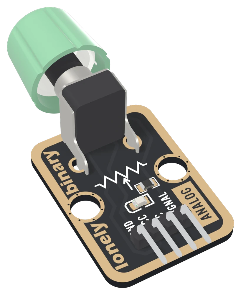
The board adds one thing a bare potentiometer does not have: a 1 kΩ resistor and a red LED from the wiper to GND. The LED glows as you turn up, which shows the block is powered at a glance. It also takes its current from the voltage you are measuring, and that bends the upper part of the reading: hard on 5 V, less on 3.3 V. The handbook below is mostly about how to read a knob well, and partly about that.
VCC is the top of the range
The wiper cannot go above VCC, and at the end of the turn it sits on it:
| Your board | VCC to | Full scale | The LED on the wiper |
|---|---|---|---|
| Arduino Uno | 5V | 0 to 1023 | lights about 40 % of the way round, about 3.0 mA at the end; pulls the reading low by up to about 1.3 V |
| ESP32, ESP32-S3 | 3V3 | 0 to 4095, flat above roughly 3.1 V | lights about 60 % of the way round, about 1.3 mA at the end; low by up to about 0.46 V |
| Raspberry Pi Pico | 3V3 | 0 to 4095 | lights about 60 % of the way round, about 1.3 mA at the end; low by up to about 0.46 V |
Never 5V beside a 3.3 V board. The LED figures and the size of the bend are worked out from a typical red LED rather than measured.
Which pin is which
Knob up, header at the bottom, reading left to right:
| GND | to your board's GND | the square pad: count from here |
| VCC | to 3V3 or 5V | your board's logic voltage |
| NC | nothing | not connected on the board |
| SIGNAL | to an analog pin | the wiper, 0 V to VCC |
The back prints TK08 ROTARY POTENTIOMETER and ROTARY TO ADJUST RESISTANCE instead of pin names. Turned over, the square pad is on the right, and it is still GND.
Wiring, in three lines
- GND to your board's GND.
- VCC to 5V on an Uno, 3V3 on an ESP32, ESP32-S3 or Pico.
- SIGNAL to an analog pin: A0 on an Uno, GPIO 34 on an ESP32, GPIO 4 on an ESP32-S3, GP26 on a Pico.
Leave NC unconnected.
Example
// The analog pin SIGNAL is wired to.
// Uno: A0. ESP32: 34. ESP32-S3: 4. Pico: 26.
const int POT_PIN = A0;

void setup() {
  Serial.begin(115200);
}

void loop() {
  int reading = analogRead(POT_PIN);   // 0 to 1023 on an Uno
  Serial.println(reading);
  delay(200);
}from machine import ADC, Pin
import sys
import time
# The GPIO number SIGNAL is wired to. ESP32: 34. ESP32-S3: 4. Pico: 26.
pot = ADC(Pin(4))
if sys.platform == "esp32":
pot.atten(ADC.ATTN_11DB) # widest range, roughly 0 to 3.1 V
while True:
print(pot.read_u16()) # 0 to 65535
time.sleep_ms(200)Where to start
The handbook below is ten short articles, each with a working figure. The first read is the whole build in three wires and a sketch that runs on all four boards.
If the reading crawls through the upper part of the turn, read why the top of the turn bends and then calibrating the turn.
When it doesn’t work
- Which pin do I read it on?
- An analog pin: A0 on an Uno, GPIO 34 on an ESP32, GPIO 4 on an ESP32-S3, GP26 on a Pico. On the two ESP32 boards those are ADC1 pins, which keep working when Wi-Fi is on. The classic ESP32's ADC2 pins stop reading once Wi-Fi starts.
- Should VCC go to 3V3 or 5V?
- To your board's logic voltage: 3V3 on an ESP32, ESP32-S3 or Pico, 5V on an Uno. The knob's full turn connects SIGNAL straight to VCC, so 5V on a 3.3 V board's analog pin is past its rating.
- On my Uno the upper half of the turn barely changes the reading, then it jumps. Is it faulty?
- No. The red LED hangs off the wiper, and once it lights it draws current through the track above the wiper, pulling SIGNAL down by up to about 1.3 V on 5 V. At the very end the wiper sits on VCC and the reading jumps to 1023. Calibrate with a few marks, or run VCC from 3V3, where the effect shrinks to about 0.46 V. The numbers are from a model, not a measurement.
- My ESP32 reads 4095 before the end of the turn.
- Its ADC, at the Arduino core's default setting, stops rising at roughly 3.1 V, so the last few degrees all read full scale. Nothing is wrong with the block.
- The reading jitters with the knob still.
- A few counts of wander is normal for any ADC. Keep a running average that moves an eighth of the way to each new reading. Tens of counts that follow your hand mean the SIGNAL wire is not reaching the pin.
- It reads 0, or full scale, whatever I do.
- Stuck at 0 is VCC not connected; stuck at full scale is GND not connected. Turn fully up and look at the red LED: if it never lights, the block is not powered.