This lesson uses: Arduino UNO R3 board, TinkerBlock TK89 1.8'' TFT module, jumper wires (or breadboard). Learn to drive the TFT with Arduino_GFX library; outcome: screen first shows "Hello!", then cycles "TFT Screen" and full-screen red, green, blue.
1. Install the library
Before writing code, install the Arduino_GFX library:
- Arduino IDE: Tools → Manage Libraries...
- Search: Arduino_GFX
- Find Arduino_GFX Library (moononournation), click Install
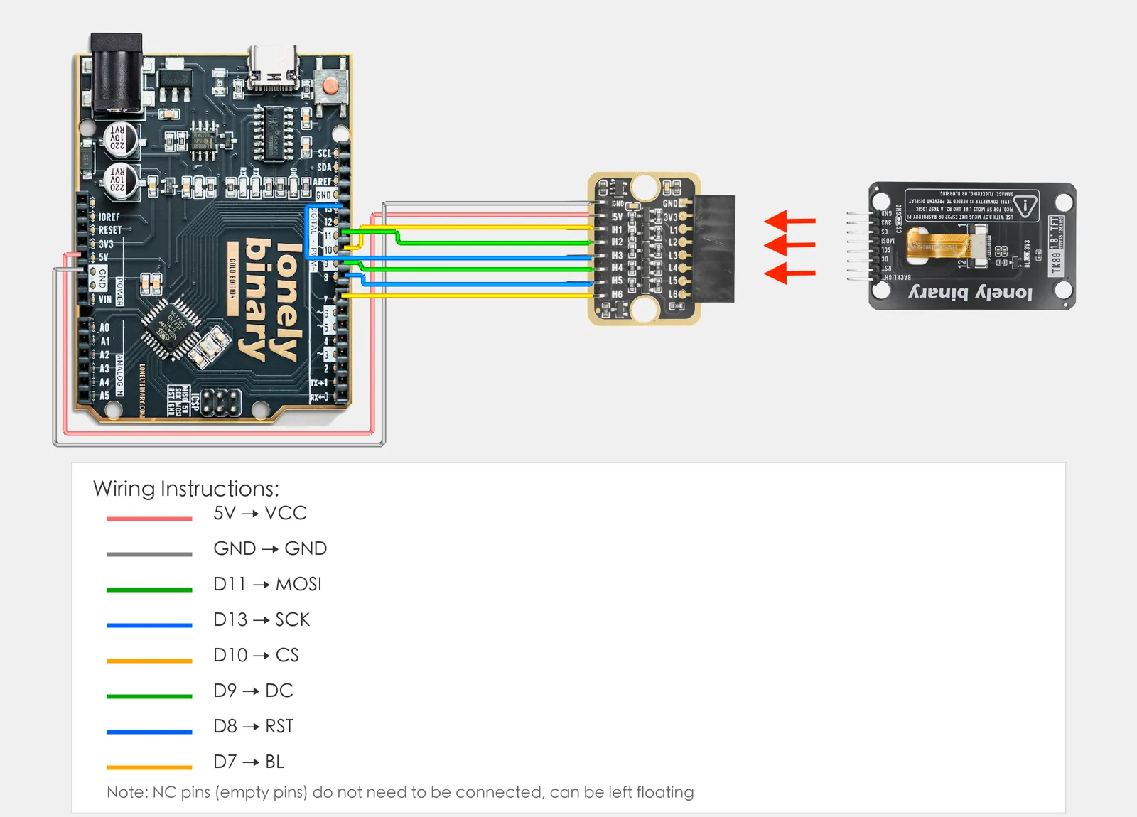
2. Wiring
Connect TK89 1.8'' TFT to Arduino:
- GND → Arduino GND
- VCC → Arduino 3.3V
- CS → Arduino D10
- RST → Arduino D8
- DC → Arduino D9
- MOSI → Arduino D11
- SCK → Arduino D13
- LED → Arduino 3.3V (backlight)
Note: If your TK89 is 3.3V logic and Arduino UNO R3 is 5V, use TK97 Logic Level Converter for level shifting to avoid damaging the display.
3. New sketch
- Arduino IDE: File → New (or Ctrl/Cmd + N) to create a blank sketch
- Confirm board and port are selected (same as Lesson 01)
- Type the code below into the default
setup()andloop()yourself
4. Program structure
Same as last lesson: two fixed blocks setup() and loop().
setup(): Include library, create display object, init display; runs once.loop(): Keep repeating “show text/graphics → wait → update → repeat”.
You’ll see "Hello!" first, then the screen will cycle red, green, blue—that’s how the small display is used.
5. Code to write
Type the code below at the top of the file and in setup() and loop() (do not copy-paste; typing it yourself helps you remember):
// 1.8" TFT (ST7735): SPI with CS/DC/RST, text and solid colors
#include <Arduino_GFX_Library.h>
#define TFT_CS 10
#define TFT_DC 9
#define TFT_RST 8

Arduino_DataBus *bus = new Arduino_HWSPI(TFT_DC, TFT_CS);
// ST7735 1.8" 128x160 (adjust offset if image is shifted)
Arduino_GFX *gfx = new Arduino_ST7735(
  bus, TFT_RST, 0 /* rotation */, false /* IPS */,
  128 /* width */, 160 /* height */,
  0 /* col offset 1 */, 0 /* row offset 1 */,
  0 /* col offset 2 */, 0 /* row offset 2 */,
  false /* BGR */);

void setup() {
  gfx->begin();
  gfx->fillScreen(RGB565_BLACK);
  gfx->setTextColor(RGB565_WHITE);
  gfx->setTextSize(2);
  gfx->setCursor(10, 10);
  gfx->println("Hello!");   // Show once on power-up
}

void loop() {
  gfx->fillScreen(RGB565_BLACK);
  gfx->setCursor(10, 10);
  gfx->println("TFT Screen");
  delay(1000);
  gfx->fillScreen(RGB565_RED);    // Red 1 s
  delay(1000);
  gfx->fillScreen(RGB565_GREEN);  // Green 1 s
  delay(1000);
  gfx->fillScreen(RGB565_BLUE);   // Blue 1 s
  delay(1000);
}
Program notes
Overall idea: TK89 uses ST7735; it talks to Arduino over SPI (CS, DC, RST, MOSI, SCK). The library’s Arduino_ST7735 handles resolution and offset; after gfx->begin() you use fillScreen for color and setCursor/println for text. This lesson shows "Hello!" in setup and in loop cycles "TFT Screen" with red/green/blue full screen.
| Code | In this lesson |
|---|---|
#include <Arduino_GFX_Library.h> | Include Arduino_GFX library |
new Arduino_HWSPI(TFT_DC, TFT_CS) | Hardware SPI bus (DC, CS; Uno default SCK/MOSI) |
new Arduino_ST7735(...) | ST7735 object; args include 128×160 and offsets (adjust if image is shifted) |
gfx->begin() | Init display and communication |
gfx->fillScreen(RGB565_xxx) | Fill screen (e.g. RED/GREEN/BLUE/BLACK) |
gfx->setCursor(x,y) / println(...) | Set text position and print string |
6. Hands-on
- After entering the code, click Verify (✓) to compile
- Click Upload (→) to upload to the board
- Watch TK89: text first, then red, green, blue in turn, repeat
- Try yourself: change text, color, position
Expected result: As in the figure.
Proceed to Lesson 25.
Edit this page — content/guides/tinkerblock-workshop/24-1-8-inch-tft-display.mdx
Questions about this product
See what other owners have asked, and read their solutions.
1.8-inch TFT Display
Loading discussions…
Discuss this article
Ask about this page. The answer stays here, on the page it belongs to, for whoever hits the same wall next.