Count from 00 to 99
Two modules, five wires, a 12 V supply and forty lines of sketch. What each part of it does, and the one number in it worth changing while you are still testing the wiring.
What you need
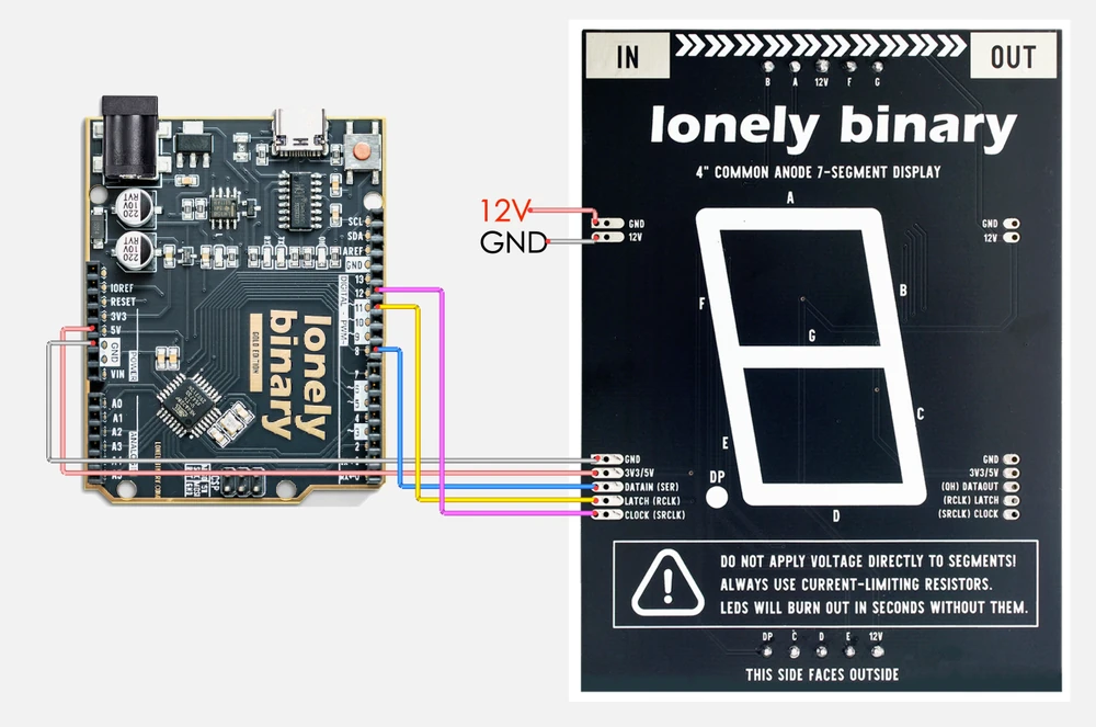
Two modules joined at the seam, five wires from an Uno to the first one's IN edge, and a 12 V supply on the two-pin header. If any of that is unfamiliar, the wiring is one page back.
The one number worth changing
STEP_MS is the delay between numbers, and it is the only thing in this sketch
that decides how long anything takes. The bits themselves go out in
microseconds.
At 400 ms a two-module chain needs forty seconds to get all the way round, and for most of that it looks like a display showing a number rather than a display counting. Turn it down to 100 while you are checking the wiring, and back up when you want to read it.
How it works, in four pieces
The table. Ten bytes, one per digit, exactly as in the byte behind a digit.
updateDisplay. Latch low, one shiftOut per module, latch high. Every
digit changes at the same instant, and it is the same three lines whether the
chain is one module or six.
The limit. limit is worked out from NUM_DIGITS rather than typed in, so
changing the module count changes what the sketch counts to and nothing else
needs touching.
The peel. t % 10 takes the rightmost digit off the number and t /= 10
throws it away, filling b[] from the right. That is the
next article.
Blanking at start-up
setup() writes 0x00 to every module before anything else. A shift register
comes up holding whatever it happens to hold, so without that line the display
shows a random pattern for as long as it takes the first count to arrive — which
looks, for a moment, exactly like a fault.
The code
Set NUM_DIGITS to the number of modules you have joined together. One counts 0 to 9, two count 00 to 99, three count 000 to 999.
// Count 00 to 99 on chained 4" seven-segment modules with a 74HC595.
//
// Wiring, at the module's IN edge (printing towards you, IN is top left):
//   12 V supply +   -> 12V            two-pin header
//   12 V supply -   -> GND            two-pin header
//   Uno 5V          -> 3V3/5V         five-pin header
//   Uno GND         -> GND            five-pin header
//   Uno D8          -> DATAIN (SER)
//   Uno D11         -> LATCH (RCLK)
//   Uno D12         -> CLOCK (SRCLK)
//
// The 12 V supply's ground and the Uno's ground must be the same wire.
// For a second module, join all seven pins of the first module's OUT edge
// to the second module's IN edge.
//
// Arduino IDE: Tools > Board > Arduino AVR Boards > Arduino Uno, then
// Tools > Port and pick the port the board appears on. No libraries.

#define NUM_DIGITS 2   // how many modules are joined together

#define SER  8         // DATAIN (SER)
#define LAT 11         // LATCH  (RCLK)
#define CLK 12         // CLOCK  (SRCLK)

#define STEP_MS 400    // how long each number stays on screen

// One byte per digit. Bit 0 is segment A, bit 6 is G, bit 7 is the point.
const uint8_t d[] = {
  0x3F, 0x06, 0x5B, 0x4F, 0x66, 0x6D, 0x7D, 0x07, 0x7F, 0x6F
};

// buf[0] is the leftmost digit. It goes out first, so it travels furthest
// down the chain and ends up in the module at the far end.
void updateDisplay(const uint8_t *buf) {
  digitalWrite(LAT, LOW);
  for (int i = 0; i < NUM_DIGITS; i++)
    shiftOut(SER, CLK, MSBFIRST, buf[i]);
  digitalWrite(LAT, HIGH);
}

void setup() {
  pinMode(SER, OUTPUT);
  pinMode(LAT, OUTPUT);
  pinMode(CLK, OUTPUT);

  uint8_t blank[NUM_DIGITS];
  for (int i = 0; i < NUM_DIGITS; i++) blank[i] = 0x00;
  updateDisplay(blank);   // a register powers up holding anything
}

void loop() {
  uint8_t b[NUM_DIGITS];

  unsigned long limit = 1;
  for (int i = 0; i < NUM_DIGITS; i++) limit *= 10;
  limit -= 1;             // 9, 99, 999 …

  for (unsigned long n = 0; n <= limit; n++) {
    unsigned long t = n;
    for (int i = NUM_DIGITS - 1; i >= 0; i--) {
      b[i] = d[t % 10];   // the rightmost digit of what is left
      t /= 10;            // drop it
    }
    updateDisplay(b);
    delay(STEP_MS);
  }
}
Nothing here needs a library. shiftOut() is part of the Arduino core, and the three pins are ordinary digital outputs — change them to suit your board.
When it does not work
Blank is what this sketch shows if the 12 V is missing, because setup() deliberately clears the display first. Measure 12 V at the module's 12V pin with the black probe on the Uno's GND before looking at anything else.
The inner loop has been rewritten to count upwards. It has to count down: the ones digit goes into the last slot of b[] because the last byte sent stays in the module nearest the Uno.
Either NUM_DIGITS is still 1, or the join between the two boards is not made. The sketch sends exactly NUM_DIGITS bytes, so a chain longer than that number never receives anything for its far end.
Change STEP_MS. At the 400 milliseconds it ships with, a two-module chain takes forty seconds to get from 00 back to 00, and most of that is spent looking at a display that appears not to be doing anything.
Pulling a number apart with two operators, and what happens when it has more digits than you have modules.
Show any number →Edit this page — content/books/4-inch-7-segment/count-from-00-to-99.mdx
Questions about this product
See what other owners have asked, and read their solutions.
4″ 7-Segment LED Display with 74HC595
Loading discussions…
Discuss this article
Ask about this page. The answer stays here, on the page it belongs to, for whoever hits the same wall next.