DATAOUT to DATAIN
A byte does not go to a module. It goes through one. Send a second byte and the first is pushed along into the next module, which is the whole mechanism behind a chain of any length.
The queue
The shift register has eight stages and a bit enters at one end. Clock in a ninth bit and something has to happen to the first one: it falls out of the far end, onto the pin printed (QH) DATAOUT.
Wire that pin to the next module's DATAIN and nothing is lost. It carries on into the next register, which is eight stages of exactly the same thing.
Watch the byte for the 7 land in the first module and then get pushed out of it
by the byte for the 3. Two shiftOut calls and two modules are loaded; the
first byte travelled twice as far as the second.
One latch for the whole row
Look at what the latch and clock do in that drawing: they go straight across the join, untouched, to every module at once. So does the logic rail, and so does the 12 V.
That is why the code for a chain is barely different from the code for one module:
void updateDisplay(const uint8_t *buf) {
  digitalWrite(LAT, LOW);
  for (int i = 0; i < NUM_DIGITS; i++)
    shiftOut(SER, CLK, MSBFIRST, buf[i]);
  digitalWrite(LAT, HIGH);
}
One more module is one more turn of the loop. The latch stays outside it, pulsed once, and every digit in the row changes at the same instant however many of them there are.
Plugging them together
The boards are meant to butt up against each other. Both edges have their seven holes in the same places, so two neighbours line up pin for pin across the seam, and a short length of the male header strip bridges them.
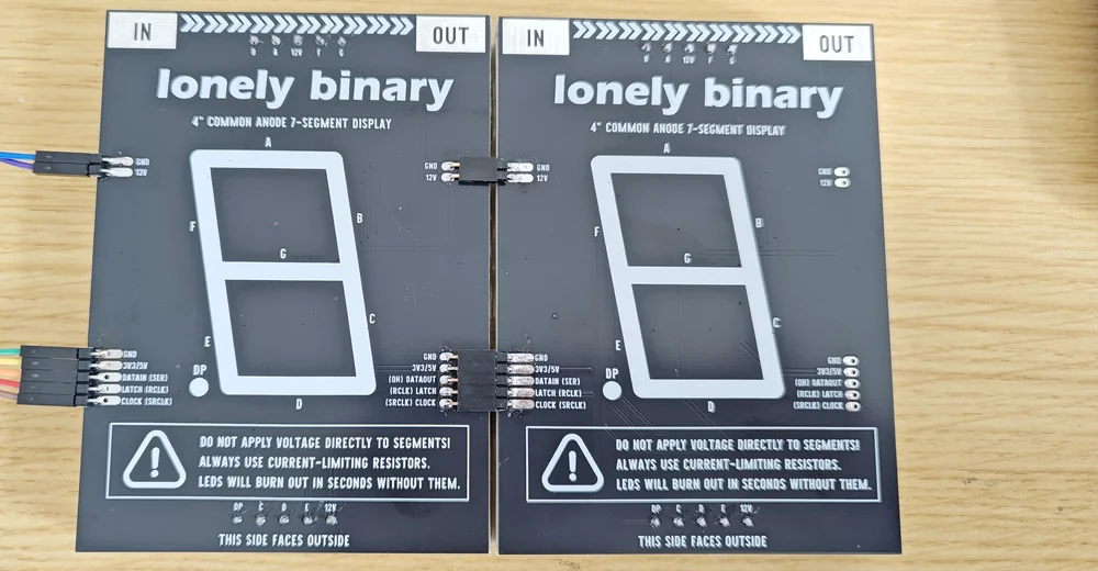
Turn that over and the two digits sit at their natural spacing with no gap between them, which is the point of joining at the edge rather than with flying leads.
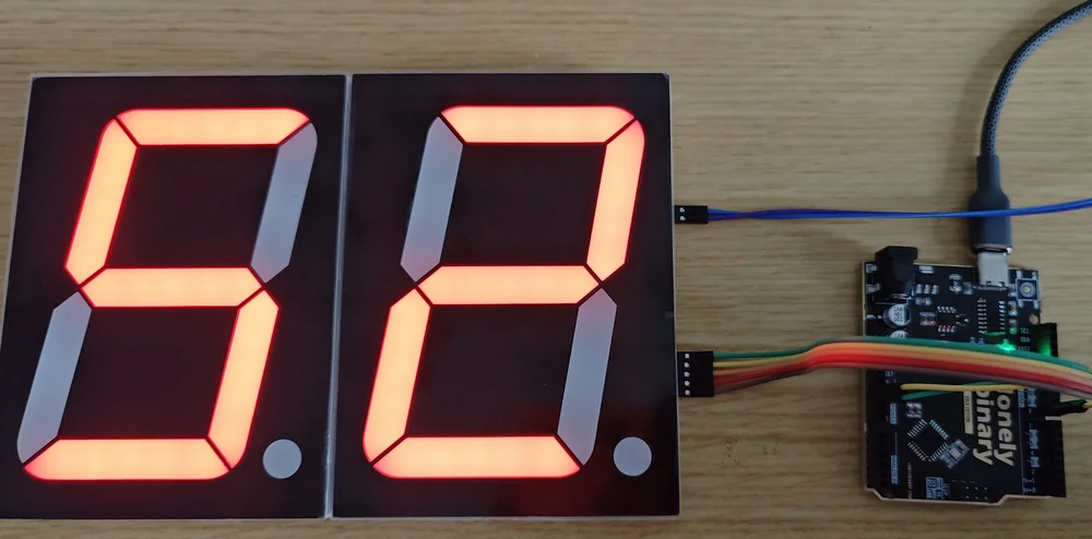
How long can it get
Nothing in the protocol has a limit. Every extra module is one more shiftOut
before the same single latch.
The real limits are ordinary ones. The 12 V supply has to carry every module in the chain, since they all draw through the join. And the wires between your microcontroller and the first module are carrying a clock, which is the one signal here that would rather be short.
When it does not work
The link between the two boards is not made. Data leaves on DATAOUT and enters the next board on DATAIN; it does not go back to your microcontroller. Check that the OUT edge of the first is joined to the IN edge of the second, and that both sets of joints are soldered.
It is doing exactly what it is built to do — you are sending the bytes in the wrong order. The byte sent first ends up furthest down the chain, so the leftmost digit has to go out first. The next article is about nothing else.
No. The 12 V and its ground pass straight across the board from the IN edge to the OUT edge, so joining two modules feeds the second one from the first. What a long chain needs is a supply that can deliver enough current for all of them, not a second supply.
Yes, and it is how you space digits apart or bend a display round a corner. Carry all seven connections across — both grounds, the logic rail, the 12 V, clock, latch, and DATAOUT to the next DATAIN — and keep the runs short, because a clock edge on a long unshielded wire is the one signal here that minds.
The module wired to your board is the right-hand one, and it holds the byte you sent last. That surprises everybody once.
Which module shows the ones →Edit this page — content/books/4-inch-7-segment/data-out-data-in.mdx
Questions about this product
See what other owners have asked, and read their solutions.
4″ 7-Segment LED Display with 74HC595
Loading discussions…
Discuss this article
Ask about this page. The answer stays here, on the page it belongs to, for whoever hits the same wall next.