Which module shows the ones
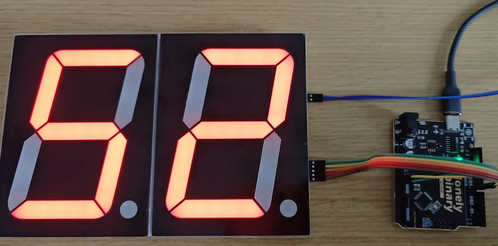
The module your wires go to holds the byte you sent last, and it is the one on the right when the digits face you. So the ones digit goes out last, and buf[0] is the digit on the far left.
The rule
Each byte you send pushes the ones before it further along. So after the last
shiftOut, the byte that is still sitting in the module nearest your board is
the one you sent last.
That module is on the right. The board's IN edge faces right when the digits face you, so every module you add goes to its left, and a number written left to right lands correctly — provided the first byte out is the leftmost digit.
Send 73 with buf[0] holding the 7 and it reads 73. Switch the second control
and put the ones digit in buf[0] instead: the same hardware, the same wires,
and the display reads 37. Nothing is miswired. The 3 simply left the pin first
and therefore travelled furthest.
In the loop
That is why the sketch's digit-peeling loop counts down:
for (int i = NUM_DIGITS - 1; i >= 0; i--) {
  b[i] = d[t % 10];   // the rightmost digit of what is left
  t /= 10;            // drop it
}
t % 10 gives the ones digit, and it goes into the last slot of the array —
because the last slot is sent last, and the last byte sent is the one that stays
nearest your board.
Written the other way round it would still compile, still run, and still light every segment. It would just print the number backwards.
Sanity check before you write a clock
Send a number whose digits are all different — 12, or 123 — rather than 11 or 88. Two identical digits will read correctly whichever way round the array is filled, which is a fine way to convince yourself the wiring is right and then discover otherwise an hour later.
When it does not work
The array is filled the wrong way round. The byte you send first travels furthest, so it finishes in the module at the far end of the chain — the left of the row. Put the leftmost digit in buf[0] and the ones digit in the last slot.
Not without turning a module over. The IN edge is on the right when the digits are facing you, and the OUT edge on the left, so a chain can only grow leftwards from the module you wire. Which is the direction a number grows anyway, so it works out.
NUM_DIGITS is still 2, so the loop sends two bytes for three registers and everything lands one module short. The count in the sketch has to match the count on the desk; the chain has no way to tell you it is longer than you think.
Send 0x00 for it. All eight bits clear means every segment off, which reads as a gap rather than a nought — useful for leading zeros, and for parking the leftmost digit until a number needs it.
The whole sketch, wired to two modules, with the one line worth changing.
Count from 00 to 99 →Edit this page — content/books/4-inch-7-segment/which-module-is-the-ones.mdx
Questions about this product
See what other owners have asked, and read their solutions.
4″ 7-Segment LED Display with 74HC595
Loading discussions…
Discuss this article
Ask about this page. The answer stays here, on the page it belongs to, for whoever hits the same wall next.