Solder the headers first
The headers come loose in the bag. A jumper pressed into a bare hole is a contact whose resistance changes when the wire moves, and every symptom it causes looks exactly like a bug in your sketch.
The one assembly step
Open the box and the modules have no connectors on them. The header strips are loose, and both edges of every board are bare plated holes. Soldering them is not optional and it is not a refinement: it is the difference between a display that works and a display that works sometimes.
The temptation is obvious, because the holes are exactly the size of a jumper wire and a wire pushed into one does make contact. It makes a contact of unknown, changing resistance, which is not the same thing.
Run it with the wire pushed in. Eight bits go past the joint one at a time and the joint only has to fail on one of them; the ones that get through are fine and the ones that do not read as zero. What comes out is a byte that is not the byte you sent, which lights a digit that is not the digit you meant — and looks for all the world like a mistake in your segment table.
What to solder
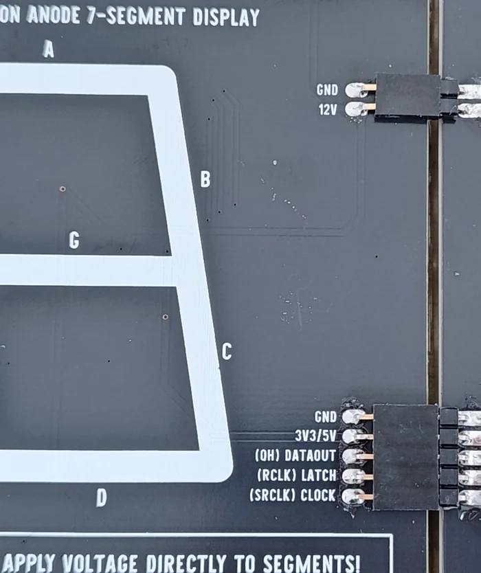
On the IN edge, all seven pins: the two-pin power header and the five-pin signal header. On the OUT edge, the same seven if you are chaining, and you can skip them if you are not.
Pins on the printed side, plastic against the board, so the pins stand clear of the back where jumper wires can reach them. Keep the orientation the same on every module — two neighbours line up pin for pin across the seam that way, and a short length of the male strip bridges them directly.
How long it takes
A few minutes a module. Fourteen joints if you are fitting both edges, seven if you are not, and none of them are fine work: the pads are large, well spaced, and forgiving of a beginner's iron.
Do it before the 12 V goes anywhere near the bench. Soldering a board that is powered is how you find out which of your jumper wires was in the wrong row.
When it does not work
That is the signature of a pressed-in connection. A soldered joint does not care how the board is held; a wire wedged in a hole is a contact whose pressure changes with every nudge, so the fault follows the movement rather than the code.
On the IN edge, yes — all seven are connections you use. On the OUT edge you can leave the headers off entirely if you are only ever running one module, and fit them later when a second one arrives. Nothing on the board minds a bare OUT edge.
This is the one step there is no way round: the board ships with bare through-holes and no connector fitted to any of them. A basic 25 to 40 watt iron and a reel of thin leaded solder is enough, and each module takes a few minutes.
Pins on the printed side, plastic spacer against the board, so they stand off the back where your jumpers can reach them. If you are chaining, the same orientation on every module makes two neighbours line up pin for pin across the seam.
What the 74HC595 actually does with the bits, and why there are two clocks instead of one.
Shift, then latch →Edit this page — content/books/4-inch-7-segment/solder-the-headers.mdx
Questions about this product
See what other owners have asked, and read their solutions.
4″ 7-Segment LED Display with 74HC595
Loading discussions…
Discuss this article
Ask about this page. The answer stays here, on the page it belongs to, for whoever hits the same wall next.