Specifications
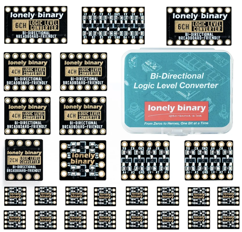
| In the 27-pack | 27 boards: 18 × 2-channel, 6 × 4-channel, 3 × 6-channel MOSFET boards, and a storage case |
|---|---|
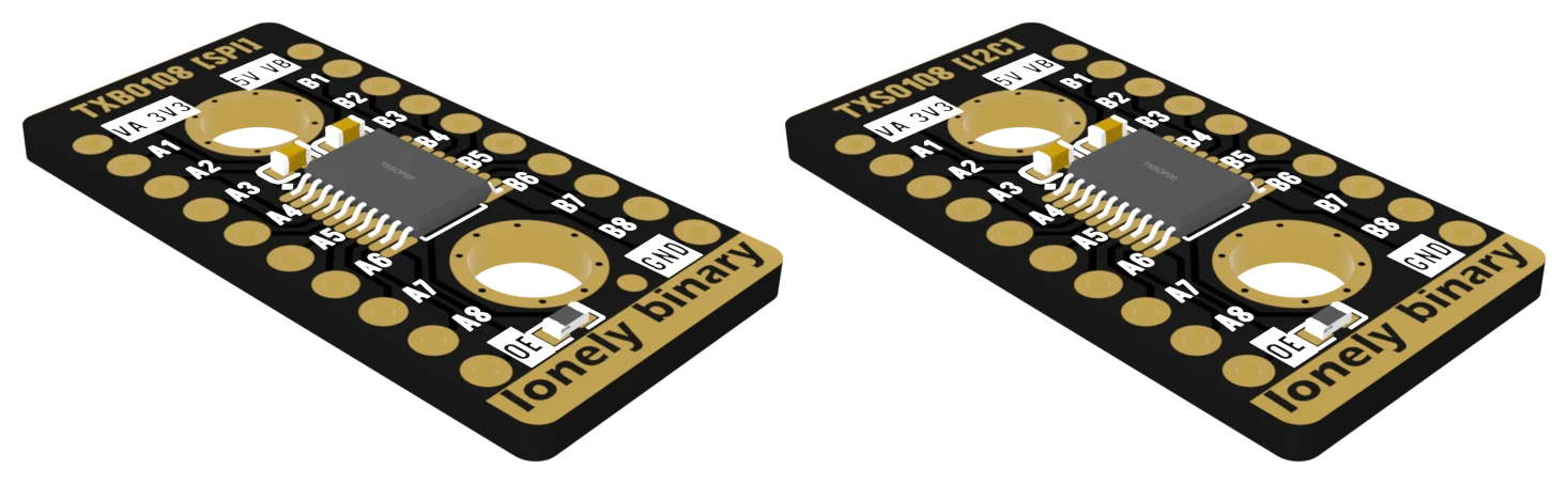
| In the 6-pack | 3 × TXB0108 and 3 × TXS0108 8-channel boards, and a storage case |
| Voltages | 3.3 V on the low side, 5 V on the high side, as printed. The low side must never be the higher of the two |
| MOSFET channel | One BSS138 transistor and two 10 kΩ pull-up resistors, one to each side |
| TXB0108 | Push-pull signals only: SPI, serial, LED data. Up to 100 Mbps at 3.3 V to 5 V. Not for I²C or 1-Wire |
| TXS0108E | Pull-ups built in: 4 kΩ passing a high, 40 kΩ passing a low. I²C and 1-Wire up to 1.2 Mbps, push-pull up to 110 Mbps |
| Chip supply ranges | TXB0108: VA 1.2–3.6 V, VB 1.65–5.5 V. TXS0108E: VA 1.4–3.6 V, VB 1.65–5.5 V. VA ≤ VB on both |
| OE (TXB and TXS) | Pulled up to VA through 10 kΩ on the board, so leaving it unconnected means on. Wiring it to GND turns every channel off |
| Ground | MOSFET boards: a GND on each side, joined on the board. TXB and TXS boards: one GND, on the B side |
| Pitch | 2.54 mm (0.1 in), two rows that straddle a breadboard's centre channel |
What it does
A 3.3 V board — an ESP32, a Raspberry Pi, a Pico — and a 5 V part disagree about what a HIGH is. Wire a 5 V output straight to a 3.3 V pin and current flows into that chip's supply through a protection diode never meant to carry it. It usually keeps working for a while, which is why people think it is fine.
A converter sits in the wire. Each side is powered by its own voltage, and a signal that goes in as 0–3.3 V on one side comes out as 0–5 V on the other — in either direction, with no direction pin to set.
![All five converter boards side by side, to scale, seen from above: the small square 2-channel board, the 4-channel and 6-channel boards, and the two longer 8-channel boards labelled TXB0108 [SPI] and TXS0108 [I2C], each with A pins down the left edge and B pins down the right.](/modules/llc/family.webp)
The two boxes
The 27-pack is one circuit in three sizes: eighteen 2-channel boards, six 4-channel and three 6-channel. Each channel is one BSS138 transistor and two 10 kΩ resistors. It is the one for I²C, serial, buttons and anything slow.
The 6-pack is two chips from Texas Instruments on the same 8-channel board: three TXB0108 and three TXS0108. They look identical and follow opposite rules. The silkscreen says which job each is for — SPI on the TXB, I2C on the TXS — and that label is the most important thing on either board.
Which board for which job
| Connecting | MOSFET 2/4/6CH | TXS0108 | TXB0108 |
|---|---|---|---|
| I²C sensor or screen | yes | yes | no |
| Serial (UART) | yes | yes | yes |
| SPI display or SD card | slow clocks only | yes | yes |
| WS2812 LED strip | marginal | yes | yes |
| DS18B20 (1-Wire) | yes | yes | no |
| Button or switch | yes | yes | no |
The three noes are one rule. The TXB holds each line with a weak drive of its own, and a pull-up resistor on the same line fights it. I²C, 1-Wire and a button all depend on pull-ups. Which board for which job explains every row.
Wiring, in four lines
- LV (or VA) to the 3.3 V board's 3V3 pin.
- HV (or VB) to the 5 V part's supply.
- GND to both boards' ground.
- Then signals: the 3.3 V board's pin to A1, the 5 V part's pin to B1.
The low side must be the lower voltage. Swap LV and HV and the A pins — the ones wired to your 3.3 V board — idle at 5 V, which is the exact thing a converter is there to prevent. On the TXB and TXS it is also more than the chip's own A side is rated for.
On the TXB and TXS boards there is only one GND, bottom right on the B side. The pin opposite it is OE, not a second ground. Leave it unconnected — the board already pulls it up, which switches the chip on. Power before signals has the whole header.
Where to start
The handbook below is eleven short articles with a working figure in each. If you only read one, read which board for which job. If your project is a 5 V I²C screen on an ESP32, that build is written out start to finish.
When it doesn’t work
- Nothing gets through the converter.
- Check the three power wires before any signal wire: LV to the 3.3 V board's 3V3, HV to the 5 V part's supply, and GND joining both boards. A converter with only one side powered passes nothing and looks broken. On a TXB or TXS board, also check that OE is not wired to GND — it sits exactly where a second ground pin would be, and grounding it switches off all eight channels.
- My I²C sensor is not found through the TXB0108.
- That is the TXB doing what its datasheet says it will. I²C lines are held high by pull-up resistors, and the TXB holds each line with a weak drive of its own that fights them; TI says any pull-up must be over 50 kΩ and names I²C as a job not to use it for. Every I²C module carries pull-ups far smaller than that. Swap to a TXS0108 or a 2-channel MOSFET board — same wiring, and it will scan.
- It works for I²C but not for my SPI display.
- You are on a MOSFET board, and SPI is too fast for it. Its rising edges are made by a 10 kΩ resistor filling the wire, which takes a few hundred nanoseconds — fine at I²C's 100 kHz, too slow for an SPI clock of several MHz. Move the SPI lines to the TXB0108, or lower the SPI clock while you test.
- Which side is which?
- A is the low-voltage side and B the high-voltage side, on every board. On the MOSFET boards the power pins are printed LV and HV; on the TXB and TXS they are VA and VB, with 3V3 and 5V printed beside them. A1 always pairs with B1, straight across the board.
- Do I need a converter to send 3.3 V into a 5 V Arduino?
- Usually not, and it is safe. An Uno reads anything above about 3 V as HIGH, so a 3.3 V signal gets through with a small margin. The other direction is the one that matters: a 5 V output into a 3.3 V pin pushes current into that chip's supply. Anything with 5 V coming towards a 3.3 V board needs a converter. The exception is a WS2812 LED strip, which wants at least 3.5 V and is the common 5 V part most likely to misread a 3.3 V pin.
- Can a converter power my 5 V part?
- No. LV and HV are references, not supplies — the converter uses them to know what 3.3 V and 5 V are, and draws almost nothing from either. The 5 V part still needs its own 5 V, usually the same wire that feeds HV.