Choosing your connectors
Four interfaces, and the right answer is almost never the same one four times. Current goes on screws, logic goes on a header, and the joint that fails first is the one carrying a motor.
Decide all four at once
The interfaces are not equivalent, and the difference is what each one carries. Power in and the two motor terminals carry motor current, which on this board can reach the overcurrent trip somewhere between 2 and 3.3 A. The control header carries logic, plus VM and GND brought out; none of its signal pins is in the motor's current path.
That splits the decision. Anything in the current path wants a joint that is mechanically solid: a screw block, or solder. The control header wants a joint you can pull off and re-seat while you are still working out which GPIO went where, which is a pin header. It has no screw-block footprint anyway.
What each option is good at
Soldered wire is the lowest resistance and the most permanent. It is the right answer for a build that is finished, and the wrong one for a board that is still moving between projects.
A 2.54 mm header is removable, cheap, and what a jumper wire expects. It is also a spring contact, which is fine for logic and poor for a motor lead being shaken by the motor it feeds.
A KF301 screw block takes a bare stranded lead with no crimp and survives being pulled, which is why it is on motor products. The cost is size: about 10 mm in each direction, sitting on top of the pad names.
The common build
Screw blocks on power in, Motor A and Motor B; a pin header on the control side.
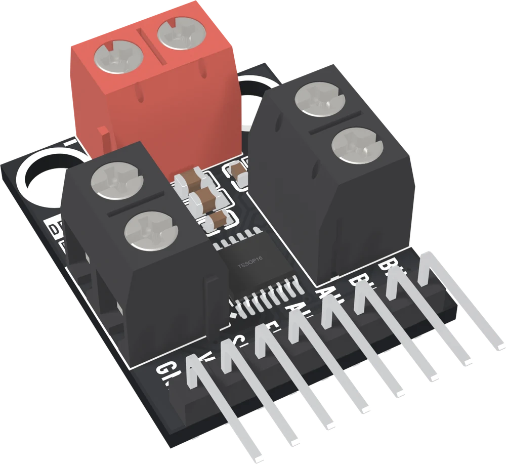
A right-angle header keeps the jumper wires flat and clear of the screw blocks, with the header's printed names still in view.
When it does not work
A 2.54 mm jumper socket is a spring contact, and a motor that jerks is a motor working to unplug itself. Intermittent motor current also looks exactly like a flat battery and exactly like a loose ground, which is why it costs an evening.
Strip about 5 mm and tighten onto bare copper, not onto insulation or a tinned tip. Solder on a stranded end creeps under pressure, so a joint that was tight last week is loose this week.
A two-way KF301 is about 10 mm wide as well as tall. If the build is tight, solder the motor leads directly, or fit the two-pin 2.54 mm header that shares each terminal's pads, and keep the removable connector for the control side.
One fact about the motor terminals decides whether two motors wired the same way agree or oppose, and the board prints it on both faces.
Which pad is OUT1 →Edit this page — content/books/drv8833/choosing-your-connectors.mdx
Questions about this product
See what other owners have asked, and read their solutions.
DRV8833 Dual Motor Driver
Loading discussions…
Discuss this article
Ask about this page. The answer stays here, on the page it belongs to, for whoever hits the same wall next.