Why it ships bare
No screw terminals, no header, nothing soldered. The connectors travel loose in the bag because each interface has two footprints, and which one it gets is a decision about your build rather than ours.
Every power interface has both footprints
The power input and both motor outputs each carry two footprints, joined pad to pad: one for a KF301 screw block at 5.0 mm pitch, and one for a two-pin 2.54 mm header. The control header has one footprint, eight pins at 2.54 mm. Nothing is fitted to any of them.
That is what makes the choice per interface rather than per board. Screw terminals on the motors, where a lead gets pulled; a pin header on the control side, where a jumper goes to a dev board and nothing tugs at it. A board that arrived with either one soldered would have made that decision for every build.
What a fitted block covers
A KF301 block is about 10 mm of plastic, and it sits on top of the silkscreen naming the pads under it. Once the three blocks are on, the top of the board no longer says AOUT1, BOUT2, GND or VM, and the MAX 10.8V under the power terminal is gone too.
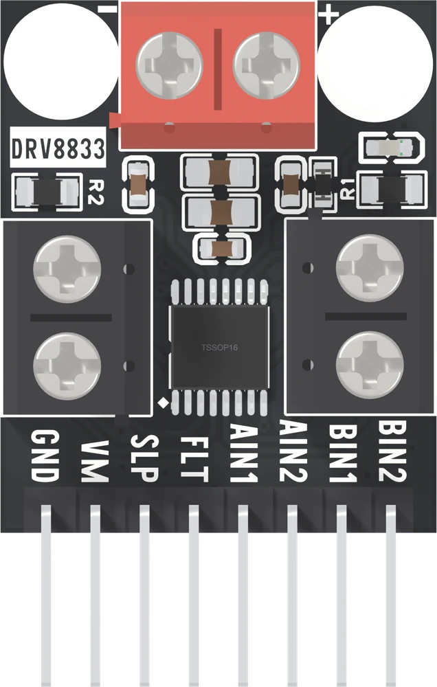
The names are not lost. The back of the board prints VM and GND beside the power pads and a 1 above a 2 beside each motor's pads, and no connector goes over them. Turning the board over answers the question at any time.
When it does not work
That is the product. The screw blocks and the header travel loose so that you choose which interface gets which, and so that a build that wants wires soldered straight to the pads is not fighting a connector somebody else chose.
On the top they do. Turn the board over: the back prints 1 above 2 beside each motor's pads and VM and GND beside the power pads, and nothing is fitted over those. The header pins on the back are unnamed, but pin 1 is the square pad.
Yes, and it is the lowest-resistance joint of the three options. It is also the one you cannot undo without a hot iron and a steady hand, so decide the whole build before the first joint.
Four interfaces and a choice at each. Current goes on screws, logic goes on a header, and the joint that fails first is the one carrying a motor.
Choosing your connectors →Edit this page — content/books/drv8833/why-it-ships-bare.mdx
Questions about this product
See what other owners have asked, and read their solutions.
DRV8833 Dual Motor Driver
Loading discussions…
Discuss this article
Ask about this page. The answer stays here, on the page it belongs to, for whoever hits the same wall next.