The 26 pins, and the ones to be careful with
Thirteen holes a side: twenty-three GPIOs, 3V, GND and EN, with no 5 V pin and no GPIO 21. Thirteen of the GPIOs are free, four can only listen, five are read at the instant the chip starts, and one has the LED on it.
Reading the silkscreen
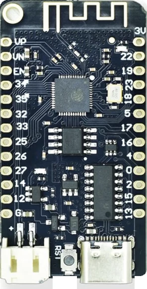
With the antenna at the top, the left row reads VP, VN, EN, 34, 35, 32, 33, 25, 26, 27, 14, 12, G, and the right row 3V, 22, 19, 23, 18, 5, 17, 16, 4, 0, 2, 15, 13. VP is GPIO 36 and VN is GPIO 39 — the shields print them as numbers, and the V can look like a U in the board's lettering. G is ground.
Wire.begin(sda, scl).Free: thirteen pins
32, 33, 25, 26, 27, 14, 19, 23, 18, 17, 16, 4 and 13. Any of them will drive an LED or read a button. Two things narrow the list for particular jobs:
- Analog readings with Wi-Fi on need ADC1. Of the free pins that is only 32 and 33; the rest are on ADC2, which the radio borrows.
- 25 and 26 are the ESP32's two DAC outputs, if you want a real voltage out.
Input only: four pins
34, 35, 36 (VP) and 39 (VN) have no output driver and no internal pull-ups. They are good analog inputs — all four are on ADC1 — and poor button pins unless you add a resistor. GPIO 36 is also where the shield's battery monitor lands.
Read at boot: five pins
The chip samples 0, 2, 5, 12 and 15 at the instant it starts, and decides how to boot from what it finds. After that they are ordinary pins. The two that bite:
- GPIO 12 HIGH at power-up selects a 1.8 V supply for the flash chip, and the board does not boot. Keep anything that pulls up off it.
- GPIO 0 LOW at power-up means "wait for an upload" rather than "run the sketch". That is useful on purpose and baffling by accident.
5 is pulled up inside and is the default SPI chip-select, which is a job that suits it.
Busy: power, ground, reset and the LED
3V is 3.3 V from the board's regulator and the only supply on the header. There is no 5 V pin, so a 5 V part needs its own supply. EN is the reset line. GPIO 22 has the on-board LED, lit when the pin is LOW.
I²C and SPI
The Arduino core's SPI pins are 18, 19, 23 and 5, and all four are here. Its I²C pins are 21 and 22 — and 21 is not on this board, while 22 has the LED. Pick two free pins and name them:
Wire.begin(16, 17); // SDA on 16, SCL on 17When it does not work
Something is holding a boot pin the wrong way at power-up — most often GPIO 12 pulled HIGH, which selects a 1.8 V flash supply, or GPIO 0 pulled LOW, which waits for an upload. Unplug the circuit, check that it boots, then move that wire to a free pin.
34, 35, 36 and 39 have no internal pull-up resistors. The line of code is accepted and ignored. Fit a 10 kΩ resistor from the pin to 3V, or move the button to a free pin.
25, 26, 27, 14, 4 and 13 are on ADC2, which the radio takes over. Move the sensor to 32, 33, 34, 35, 36 or 39, which are on ADC1 and work with Wi-Fi on.
The sensor is on GPIO 22, which is also the LED. It is the Arduino core's default I²C clock pin, so a sketch that calls Wire.begin() with no pins uses it. Give Wire.begin two free pins instead.
Soldering the strips straight, and the one orientation that works.
Headers on, and which way round →Edit this page — content/books/esplipo/the-26-pins.mdx
Questions about this product
See what other owners have asked, and read their solutions.
ESP32 LiPo Dev Kit: 3 Boards with LiPo Charger + 3 Shields
Loading discussions…
Discuss this article
Ask about this page. The answer stays here, on the page it belongs to, for whoever hits the same wall next.