Specifications
| In the box | 3 ESP32 LiPo boards with 6 male header strips to solder on, 3 shields (2.54 mm header, spring terminal, screw terminal) that need no soldering, 6 JST PH 2.0 cables and a storage case. No battery |
|---|---|
| Chip | ESP32-D0WDQ6: two cores at 240 MHz, 2.4 GHz Wi-Fi, Bluetooth Classic and BLE. 4 MB flash, no PSRAM |
| Battery | One 3.7 V lithium cell with its own protection circuit — a LiPo pouch or a protected 18650 — on a JST PH 2.0 plug. Not included |
| Charging | Up to 500 mA from USB-C, to 4.2 V. Use a cell of 500 mAh or more |
| Power path | Runs from USB and charges the cell at the same time. When USB is unplugged the cell takes over without a reset |
| USB | USB-C with a CH340 USB-to-serial chip, for power, charging and uploads. Some C-to-C cables work only one way up |
| Pins | 26 on a 2.54 mm grid, 13 a side. 3V and GND are the only power pins: no 5 V pin and no battery pin. GPIO 21 is not brought out |
| LED | GPIO 22, lit when the pin is LOW |
| Buttons | RST only. Uploads start the board themselves through the USB chip; there is no BOOT button |
| Battery sockets | The board's socket has + on the left, and the shield's LIPO BTT socket has + on the right, looking down with the USB end towards you. A lead that is right for one is reversed on the other |
| Shields | Each has a battery ON/OFF switch, a resettable fuse (PPTC), a LIPO BTT socket for the cell and a TO ESP32 socket for the cable to the board |
| Battery monitor | A solder pad on each shield joins a 1:2 divider across the cell to IO36 (VP). It ships open |
| Arduino IDE | Board: ESP32 Dev Module. Upload speed 921600, or 115200 if an upload stops partway |
What it does
It is a classic ESP32 with a lithium cell charger on the board. Plug a cell into its socket and USB-C does two jobs: it runs the board and charges the cell. Unplug the cable and the cell carries on running it, without a reset, so a sketch in the middle of something stays in the middle of it.
The rest of the board is a small ESP32 dev board: 26 pins, a USB-C port with a CH340 serial chip for uploads, a reset button and an LED on GPIO 22.
The box
Three boards and three shields. The boards arrive with their header strips loose, for you to solder; the shields arrive finished.
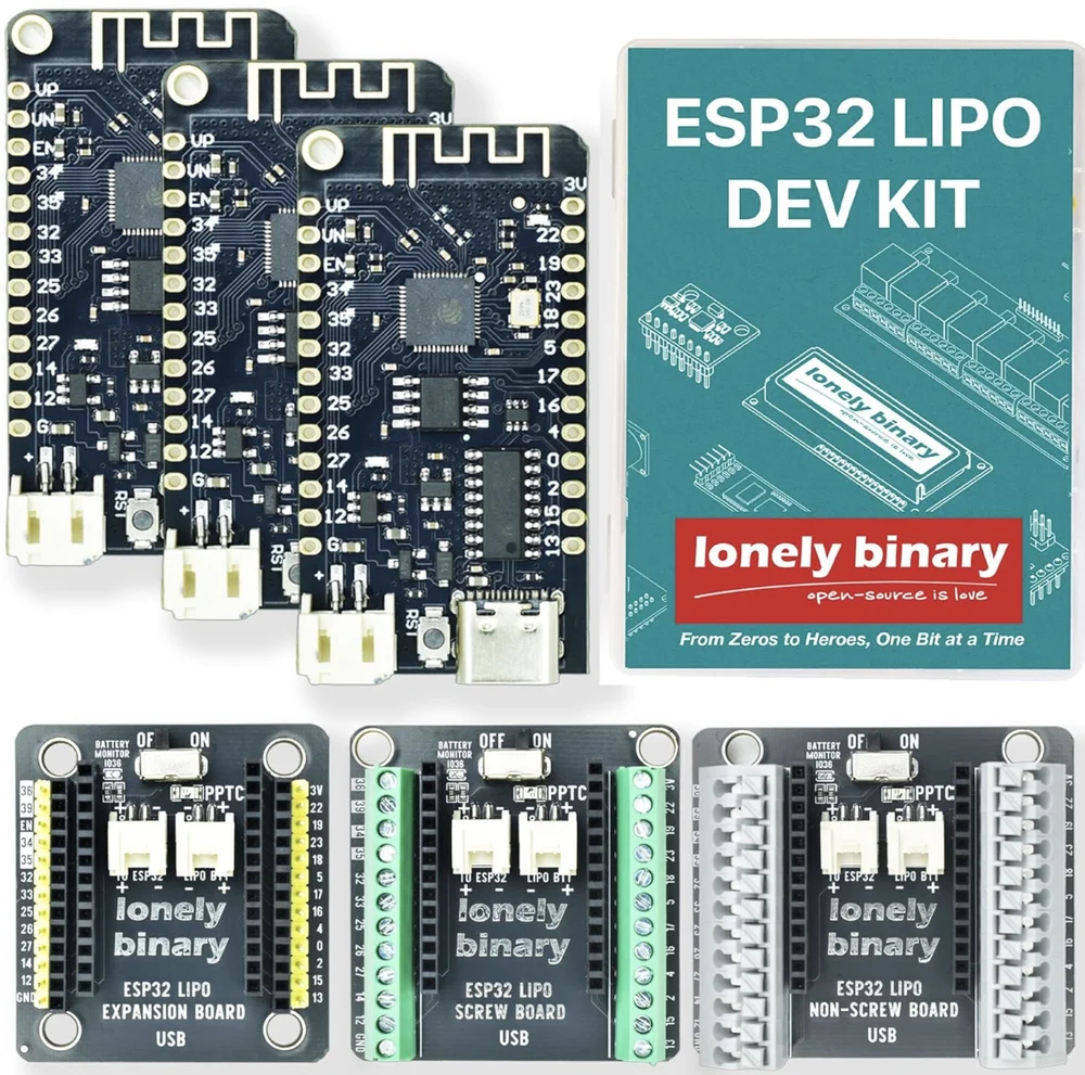
The board does the charging, the switching and the computing. It has its own battery socket, so it works on its own with a cell plugged straight in.
A shield is what the board plugs into when it becomes a project. All three have the same middle — a battery switch, a resettable fuse, a monitor pad and two battery sockets — and differ only in how they hold a wire:
| Shield | Holds | Good for |
|---|---|---|
| 2.54 mm header | Jumper wires | Breadboard work that changes every few minutes |
| Spring terminal | Stripped wire, no tool | Wiring that changes now and then |
| Screw terminal | Stripped wire, screwdriver | A finished build that gets carried or shaken |
Wiring, in four lines
- Seat the board on the shield with the antenna at the switch end and USB-C at the end printed USB.
- Cell into LIPO BTT, red wire to the + printed beside it.
- A cable from the box between the shield's TO ESP32 and the board's battery socket, + to +.
- Switch ON, then USB-C to charge or program.
The board's own socket and the shield's LIPO BTT socket are wired opposite ways round. A cell whose plug is right for one is reversed on the other, so read the + every time. Which pin is plus shows both.
The cell
One 3.7 V lithium cell, with its own protection circuit, on a JST PH 2.0 plug. A LiPo pouch of 500 mAh or more is the usual choice; a protected 18650 lasts longest. The charger delivers up to 500 mA, which is too fast for the small 100–200 mAh cells sold for tiny projects. The cell to buy has the arithmetic.
Where to start
The handbook below is thirteen short articles with a working figure in each. If you only read one before plugging in a cell, read which pin is plus. If you want the LED blinking first, blink the LED on GPIO 22 has the one setting the Arduino IDE needs.
When it doesn’t work
- Is this an ESP32-S3?
- No. It is the original ESP32 — esptool reports an ESP32-D0WDQ6 — with two cores, Wi-Fi, Bluetooth Classic and BLE. Choose ESP32 Dev Module in the Arduino IDE, and any sketch for a classic ESP32 DevKit will run, as long as it uses pins this board brings out.
- Which way round does the board go on a shield?
- Antenna at the end with the ON/OFF switch, USB-C at the end printed USB. The two rows are the same length, so it also fits turned round — and then the board's 3.3 V pin sits in the shield's GND socket. Check both ends before you connect a cell.
- My cell's plug is right for the shield but reversed on the board.
- That is how they are made: the board's socket and the shield's LIPO BTT socket are wired opposite ways round. Use the socket the plug is right for, and check the red wire against the + printed beside the socket every time. If you need the other one, the two pins lift out of the plug with a needle under each tab and swap over.
- Does it really keep running when I unplug USB?
- Yes, with a charged cell connected. The board runs from USB while it charges the cell, and when USB goes it switches to the cell without a reset. On a shield, the switch must be at ON and the TO ESP32 cable fitted, or there is no cell for it to switch to.
- Can I power a 5 V sensor from it?
- Not from the header. The only supply pin is 3V, which is 3.3 V from the board's regulator. A part that needs 5 V needs its own 5 V supply, a shared ground, and a level shifter on any signal it sends back.
- How do I read how full the battery is?
- Bridge the BATTERY MONITOR pad on the shield with a blob of solder. That joins a divider across the cell to GPIO 36, which then sees half the cell voltage. Read it with analogReadMilliVolts and double it, on battery and with the radio quiet — while USB is in, you are reading the charger, not the cell.