The battery monitor pad
Beside the switch on every shield is a pad marked BATTERY MONITOR IO36. Bridge it with solder and GPIO 36 sees half the cell's voltage, through two equal resistors. It ships open, so GPIO 36 stays yours until you decide the battery should have it.
Where it is
It is on the shield, not the board: a small rectangle of silkscreen at the top corner, beside the ON/OFF switch, with two resistors under it.
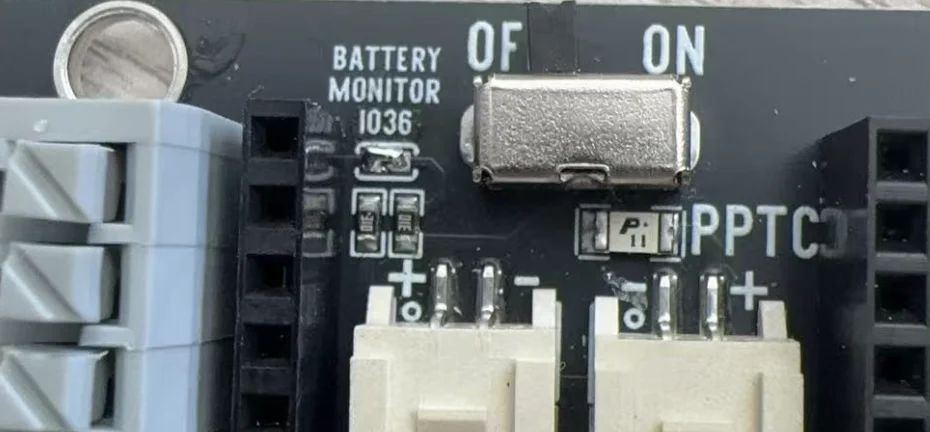
The two resistors are a divider: equal values, so the point between them is at half the cell's voltage. The pad is a gap between that point and the shield's socket marked 36, which meets the board's VP pin — GPIO 36.
What bridging does
Why halve it: a full cell is 4.2 V, and an ESP32 pin must not see more than 3.6 V. Halved, a full cell is 2.1 V, which sits inside the range the ESP32 measures most accurately at its widest setting — 150 to 2450 mV, according to Espressif's datasheet.
GPIO 36 is a good pin for it. It is input only, so it was never going to drive anything, and it is on ADC1, which keeps reading while Wi-Fi is on.
What it costs
Bridging it gives GPIO 36 to the battery for good — anything else wired to that pin now fights the divider. And the divider is a small, steady load on the cell. Its resistor values are not legible in any photo of the board, so how small is not something this page can tell you; it matters only to a project that sleeps for weeks, and a meter will say.
Bridging it
A hot iron across both halves of the pad at once, and a little solder fed in until it flows over both. The result is a small shiny dome with no gap. Solder bridges are usually the fault; here it is the point.
When it does not work
Check three things: the solder really joins both halves of the pad (look under a light); the switch is at ON; and the board is seated antenna at the switch end. Turned round, the shield's 36 socket holds the board's GPIO 13, not 36.
Then leave the pad open, or open it again: touch it with solder wick and a hot iron until the blob lifts away, and check there is a visible gap. With the pad bridged, anything else on GPIO 36 is fighting the divider.
Add a little flux, put the iron across both halves at once, and feed solder into the joint rather than onto the iron. A clean bridge is a small shiny dome over both pads.
Not with this pad — the divider is on the shield, not the board. Build one from two equal resistors between the cell's + and GND, with the middle to any ADC1 pin: 32 to 39.
Sixteen calibrated readings, doubled, and one number from a meter.
Read the cell on IO36 →Edit this page — content/books/esplipo/the-battery-monitor-pad.mdx
Questions about this product
See what other owners have asked, and read their solutions.
ESP32 LiPo Dev Kit: 3 Boards with LiPo Charger + 3 Shields
Loading discussions…
Discuss this article
Ask about this page. The answer stays here, on the page it belongs to, for whoever hits the same wall next.