A screen on four wires
A 1602 is a sixteen-pin part from 1987. The chip on the back of this one turns those sixteen pins into four, two of which are power — and the two that are left are shared with everything else on the bus.
A character display, not a screen
The glass shows sixteen characters across and two down. Every cell is five
dots wide and eight tall, and the shapes come out of a character table baked
into the controller. You send it the byte 0x41 and it draws an A. There is no
way to light an arbitrary dot, so there is no way to draw a logo, a graph or a
curve.
What you can do is define eight characters of your own, a cell at a time, and print them alongside the built-in ones. That is enough for a degree sign, an arrow, or a bar that fills a dot column at a time — eight characters of your own is that chapter.
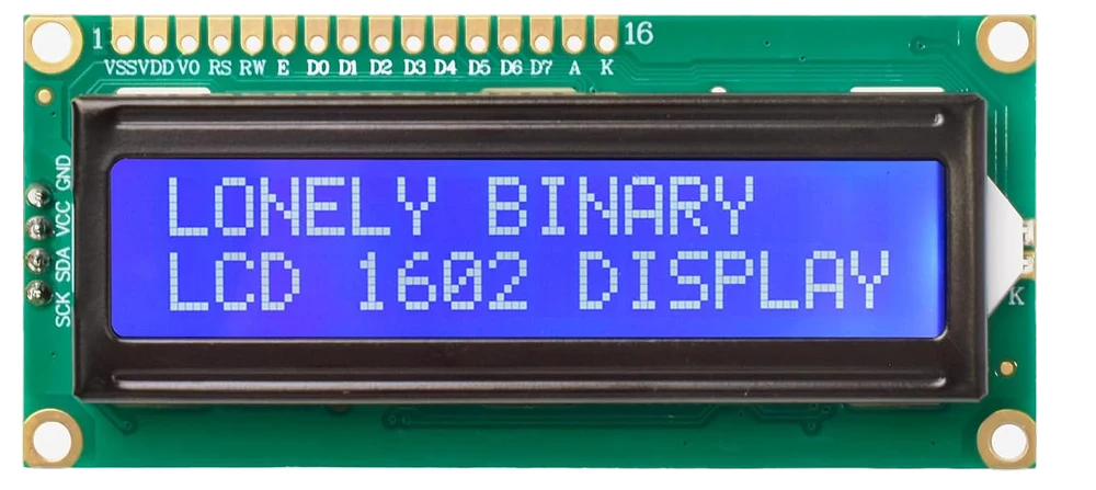
Sixteen pins, and why you never see them
The row of holes along the top is the display's real interface, and it has not changed since the Hitachi HD44780 defined it in 1987. Driving it directly costs six wires even in its economical four-bit mode, plus a supply, a ground, two more for the backlight, and a potentiometer you have to supply yourself for the contrast.
The chip on the back of this board does all of that on the board. It is an I²C port expander: two wires in, eight outputs out, and those eight outputs are wired to the six signals the controller needs plus the backlight.
What it costs you
Two signal wires, and they are the two you were going to spend anyway. SDA and SCK are a bus — every I²C part on the bench shares the same pair, so a sensor, a real-time clock and this display together still cost two pins.
The bill is paid somewhere else instead. The display is a 5 V part, and it puts 5 V on those two shared wires whenever nothing is talking. On an Arduino Uno that is exactly what the Uno expects. On an ESP32, a Pico or a Raspberry Pi it is more than the pins are rated for, and why it wants five volts is the chapter that decides whether your board survives the project.
When it does not work
That is the display's own sixteen-pin interface, and it is unpopulated on purpose. The expander chip on the back is already wired to it underneath. You never need to solder pins into it unless you want to drive the display the old way instead, and then the expander is in your way.
No. It is a character display: thirty-two fixed cells of 5 × 8 dots, and the shapes come out of a character ROM inside the controller. You can define eight characters of your own at a time, which is enough for a degree sign, an arrow or a progress bar, and nothing like enough for a logo.
No. The four-pin header on the edge is fitted at the factory, so jumper wires push straight on. The only tool you need is the screwdriver in the box, and that is for the contrast trimmer.
The expander is happy from 2.5 V, but the glass is not: below about 4.4 V there is no contrast left to adjust and the trimmer will not get it back. Run the display at 5 V and put a level converter on the two signal wires. “Why it wants five volts” is the whole argument.
The two chips, the two headers, the trimmer and the three pads that set the address.
A tour of the board →Edit this page — content/books/lcd1602/a-screen-on-four-wires.mdx
Questions about this product
See what other owners have asked, and read their solutions.
3-Pack 1602 LCD Display Module, I2C 16x2 Blue
Loading discussions…
Discuss this article
Ask about this page. The answer stays here, on the page it belongs to, for whoever hits the same wall next.