Power, and the contrast trimmer
Four wires, one library and thirteen lines of sketch. Then the part nobody writes down: the trimmer has about one turn of travel, and the readable part of it is a fraction of that.
Four wires
| Display | Arduino Uno |
|---|---|
| GND | GND |
| VCC | 5V |
| SDA | A4 |
| SCK | A5 |
The Uno's I²C pins are fixed at A4 and A5 and are not chosen in code. The display's clock pin is printed SCK on the silkscreen; it is the I²C clock, the pin every library calls SCL. Nothing on this board is SPI.
Power first, then signals. A display with SDA and SCK connected and no supply does not half-work — it does nothing, and looks exactly like a broken one.
The library
Install LiquidCrystal I2C by Frank de Brabander from the Library Manager. There are several libraries with nearly that name; this is the one every example for these boards is written against, and the one this handbook follows.
The trimmer is the first thing to check
The trimmer sets the voltage on the controller's VO pin, and that voltage is the whole of what contrast means here. It has about one turn of travel, it is easy to walk past the readable band, and it is the cause of most reports that one of these arrived dead.
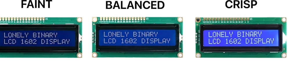
Two things the figure separates that most guides run together. Solid blocks mean the display is powered and readable, and nothing has talked to the controller yet — a new display straight out of the packet looks like this and it is correct. A blank lit screen after your sketch has run is either the trimmer or the address, and there is no way to tell them apart by looking. Turn the trimmer through its whole travel first because it takes ten seconds; if that changes nothing, go to find its address.
Then the sketch
The sketch below prints two rows and stops. Nothing is refreshed and nothing needs to be: the controller holds every cell until something overwrites it.
The code
The whole of a first display sketch. It draws two rows once in setup() and leaves loop() empty, because whatever you print stays lit until something overwrites it — there is nothing to refresh.
// Wiring (Arduino Uno — a 5 V board, so no level converter):
//
//   LCD GND -> GND
//   LCD VCC -> 5V
//   LCD SDA -> A4
//   LCD SCK -> A5        (the silkscreen says SCK; it is the I2C clock)
//
// Arduino IDE: Tools > Board "Arduino Uno", then
//   Sketch > Include Library > Manage Libraries...
//   search "LiquidCrystal I2C", install the one by Frank de Brabander.
//
// On a 3.3 V board read /manuals/lcd1602/wiring-it-to-an-esp32 first.

#include <Wire.h>
#include <LiquidCrystal_I2C.h>

// Address, columns, rows. 0x27 is what these boards ship as.
LiquidCrystal_I2C lcd(0x27, 16, 2);

void setup() {
  lcd.init();       // wake the controller and put it in 4-bit mode
  lcd.backlight();  // the backlight is an expander output, not a wire

  // setCursor(column, row). Both count from 0.
  lcd.setCursor(0, 0);
  lcd.print("LONELY BINARY");
  lcd.setCursor(0, 1);
  lcd.print("LCD 1602");
}

void loop() {
  // Nothing. The glass holds what was written to it.
}
Solid blocks after this uploads mean the sketch never reached the display: check the address with /manuals/lcd1602/find-its-address. A blank glowing screen after this uploads almost always means the trimmer, not the code.
When it does not work
Turn the trimmer. Go slowly and go both ways — the readable band is a small part of one turn, and it is easy to walk straight past it. If neither end of the travel shows anything at all, the sketch is not reaching the display and the address is the next thing to check.
That is what the glass shows before anything initialises the controller. It means the display has power and the contrast is set where you can read it — both good news. If the blocks are still there after this sketch uploads, nothing reached the controller: wrong address, or SDA and SCK swapped.
Then stop. It is a single-turn part and forcing it past the stop shears the wiper. Use the small screwdriver from the box rather than a large one, and turn from the other end if you have run out of travel in one direction.
No power. Measure 5 V between the display's own VCC and GND pins rather than on the breadboard rail, because the commonest cause is a jumper that is in the row next to the one you meant.
The backlight draws steadily and the controller is fussy about its supply. Sharing a supply with a motor drops the rail under load. Give the motor its own supply and join the grounds.
0x27, why it is 0x27, and how to make three displays share one pair of wires.
Find its address →Edit this page — content/books/lcd1602/power-and-the-contrast-trimmer.mdx
Questions about this product
See what other owners have asked, and read their solutions.
3-Pack 1602 LCD Display Module, I2C 16x2 Blue
Loading discussions…
Discuss this article
Ask about this page. The answer stays here, on the page it belongs to, for whoever hits the same wall next.