A tour of the board
Two chips that know nothing about each other, joined by eight wires somebody chose. Everything that surprises you later is on this board, and most of it is on the back.
The front is the part you read
A green board, 80 × 36 mm, which is the standard 1602 outline — the mounting holes line up with any enclosure cut for one. The glass behind the black frame is 64 × 14 mm of readable area, white characters on a blue field.
Down the left edge, four pins already soldered: GND, VCC, SDA, SCK. Along the top edge, sixteen empty holes — the controller's own parallel interface, which the chip on the back is already using.
The back is the part you need
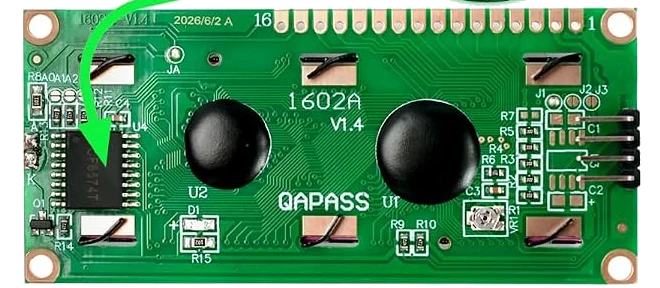
Five things on this side matter. The figure names them one at a time.
Two of them come back in every later chapter. The trimmer is the first thing to reach for when the screen is blank and the commonest reason a working display looks broken. The three pads are the only way to put more than one of these on a bus, because all three in the box answer to the same address out of the packet.
Two chips, two eras
The blobs in the middle are an HD44780-compatible controller and its column driver, mounted as bare dice and potted in epoxy. That interface — sixteen pins, a four-bit mode, an enable pulse — was fixed in 1987 and every character LCD since has copied it.
The small chip on the left is a PCF8574T, a general-purpose I²C port expander. It is not a display part and knows nothing about displays. Somebody wired its eight outputs to the controller's pins, and a library on your board pushes bytes through it in the pattern the controller expects.
That join is the whole design, and it is where the interesting behaviour comes from: eight pins, one byte at a time unpicks it.
When it does not work
Because whoever drew the silkscreen wrote SCK. It is the I²C clock, and every library, every scanner and every other board on the bench calls that pin SCL. Wire it to your board's SCL and ignore the letter. There is no SPI on this display and nothing else the pin could be.
It is, and so does the sixteen-pin header. You are looking at the same board from two sides: pin 1 of the big header is on the left from the front and on the right from the back. Read the labels, not the positions.
The controller and its column driver, mounted as bare silicon and covered in epoxy — chip-on-board, which is cheaper than packaging them. Between them they are an HD44780-compatible controller. Nothing about them is serviceable.
Bridging a pad changes the address, so a sketch still asking for 0x27 finds nothing. Run the scanner again and use the address it prints. If the scanner finds nothing at all, check that the solder blob is on one pad pair only and has not run across to a neighbour.
Four wires, one screwdriver, and the adjustment that stands between you and a blank screen.
Power, and the contrast trimmer →Edit this page — content/books/lcd1602/a-tour-of-the-board.mdx
Questions about this product
See what other owners have asked, and read their solutions.
3-Pack 1602 LCD Display Module, I2C 16x2 Blue
Loading discussions…
Discuss this article
Ask about this page. The answer stays here, on the page it belongs to, for whoever hits the same wall next.