Specifications
| In the box | 3 displays, 3 snap-on black front bezels and 1 mini screwdriver for the contrast trimmer |
|---|---|
| Characters | 16 columns × 2 rows, each cell 5 × 8 dots. White characters on a blue backlight |
| Interface | I²C on 4 pre-soldered pins — GND, VCC, SDA and SCK. The 16-pin parallel header is present but unpopulated |
| I²C address | 0x27 as shipped. The A0, A1 and A2 solder pads take it down to 0x20, so eight displays can share one bus |
| Supply voltage | 5 V. The expander alone runs from 2.5 V, but below about 4.4 V the glass has no contrast left to adjust |
| Bus speed | 100 kHz. That is what the PCF8574 is specified to, and a faster clock is the commonest cause of characters that are nearly right |
| Expander | PCF8574T, 8-bit I²C port expander. 4 outputs carry the data nibble, 3 carry RS, RW and E, and 1 switches the backlight |
| Controller | HD44780-compatible, chip-on-board. 80 characters of display memory as 2 rows of 40, and 8 writable characters of 5 × 8 dots |
| Board | 80 × 36 mm and 12 mm thick, the standard 1602 outline and mounting holes. Readable glass 64 × 14 mm |
| 3.3 V boards | Need a level converter on SDA and SCK. The board's pull-ups go to its own 5 V supply, so the bus idles at 5 V |
What it does
Sixteen characters across and two down, on four wires. The display itself is an HD44780-compatible character panel — the same interface every 1602 has had since 1987 — and the chip on the back is a PCF8574T I²C port expander wired to it. Two wires in, sixteen pins driven on the board.
It is a character display. Every cell is five dots wide and eight tall, and the shapes come out of a table inside the controller. You cannot draw a picture on it. You can define eight characters of your own at a time, which is enough for a degree sign, an arrow, or a bar that fills a dot column at a time.
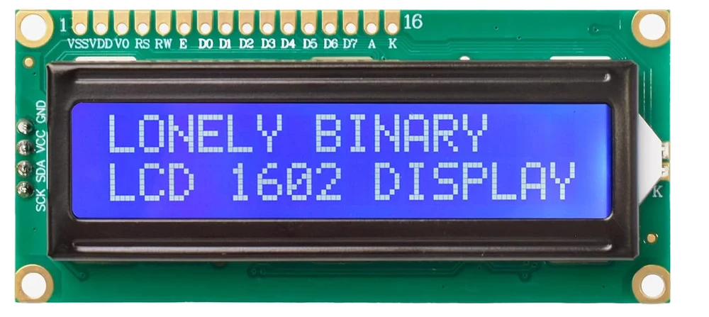
What is in the box
Three displays, three snap-on black bezels that cover the bare PCB edge for a panel-mount finish, and one mini screwdriver for the contrast trimmer. All three displays ship at address 0x27, so the second one you plug in will fight the first until you bridge a pad.
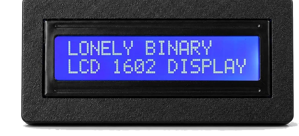
Wiring, in four lines
- GND to your board's ground.
- VCC to 5 V. Not 3.3 V — see below.
- SDA to your board's SDA.
- SCK to your board's SCL. The silkscreen spells the clock pin SCK; it is the I²C clock.
On an Arduino Uno, Nano or Mega that is the whole job: SDA is A4 and SCL is A5, and the bus idles at 5 V, which is what those boards expect.
On an ESP32, a Pico or a Raspberry Pi, put a 2-channel level converter in the two signal wires first. The board's pull-up resistors go to its own supply, so a 5 V display makes a 5 V bus whatever your sketch does, and that goes straight into pins rated for 3.3 V.
Which chip does what
| PCF8574T | The I²C side. Its address is 0x20 plus the three address pins, which are held high, so 0x27. Specified to a 100 kHz bus clock. |
| HD44780-compatible controller | The display side. 80 characters of memory as two rows of 40, of which 16 of each are lit, and 8 writable characters of 5 × 8 dots. |
| VR1 | The contrast trimmer. About one turn of travel, and the cause of most blank screens. |
| A0 A1 A2 | Three solder pads. Bridging one pulls that address bit low, so the address counts down from 0x27. |
Where to start
The handbook below is eleven short articles with a working figure in each. If you read one, read why it wants five volts — it is the page that decides whether your ESP32 survives the project. If the screen is already blank, when the screen stays blank is the ordered check.
When it doesn’t work
- The backlight is on and the screen is blank.
- Turn the contrast trimmer on the back, slowly, through its whole travel in both directions. It has about one turn of movement and the readable band is a small part of it — this is the commonest report of a dead display by a wide margin, and it takes ten seconds to rule out. If neither end of the travel shows anything, run an I²C scan next: the address is the only other likely cause.
- It shows a row of solid blocks.
- That is what the glass looks like before anything initialises the controller, and it is good news twice over — the display has power, and the contrast is set where you can read it. If the blocks are still there after your sketch has run, nothing reached the controller: the address is wrong, or SDA and SCK are swapped.
- Why does the header say SCK instead of SCL?
- Because that is what the silkscreen says. It is the I²C clock, and every library, scanner and other board calls the same pin SCL. There is no SPI on this display and nothing else that pin could be.
- Tutorials say to try 0x3F. It does not work.
- 0x3F belongs to the PCF8574A, a different part whose base address is 0x38. This board carries the plain PCF8574T, so its address can only be 0x20 to 0x27 — 0x27 as shipped, and lower if you bridge one of the pads. If nothing in that range answers a scan, the fault is not the address.
- Can I wire it straight to an ESP32 or a Pico?
- No. I²C lines are held high by resistors, this board's go to its own VCC, and at 5 V that means SDA and SCK idle at 5 V against pins rated for 3.6 V. It often works for weeks, which is why people believe it is fine. Put a 2-channel MOSFET converter or a TXS0108 between them — not a TXB0108, which fights the pull-ups an I²C bus depends on.
- Can I power the whole thing from 3.3 V instead?
- It fixes the bus and breaks the screen. The expander is happy from 2.5 V, but the contrast comes from the voltage across the liquid crystal and there is not enough of it below about 4.4 V. The expander also wants 0.7 × VCC to read a HIGH, so neither direction is in specification. 5 V and a converter is the answer.
- Nothing works on my ESP32 and the scanner finds nothing either.
- Check the order of two lines in setup(). The library calls Wire.begin() with no arguments inside lcd.init(), and on the ESP32 the first call to start the bus decides the pins — so lcd.init() first puts the bus on the board's defaults and your own Wire.begin(sda, scl) is ignored without a word. Start the bus yourself first.
- Can I use all three on one board?
- Yes, once they stop sharing an address. Out of the packet all three answer at 0x27, so writing to one writes to all of them. Bridge A0 on the second and A1 on the third, rescan, and give each its own address in the sketch.