Find its address
Every display in the box answers to 0x27, which is fine until you own two. Three solder pads change that, and the address they make is arithmetic rather than folklore.
0x27, and where it comes from
The expander's address is not a setting. It is the three address pins, read
straight into the bottom of the byte: the chip answers to 0 1 0 0 A2 A1 A0,
which is 0x20 plus whatever those three pins are. On this board all three are
held high and the pads that could pull them low are open, so the address is
0x27.
That is why every sketch for these displays starts at 0x27, and why all three displays in the box answer there.
Three pads, eight addresses
Each pad is a pair of exposed copper rings. Bridge one with a blob of solder and that address bit goes low, so the address counts down from 0x27: bridge A0 and it is 0x26, bridge A1 and it is 0x25, bridge both and it is 0x24.
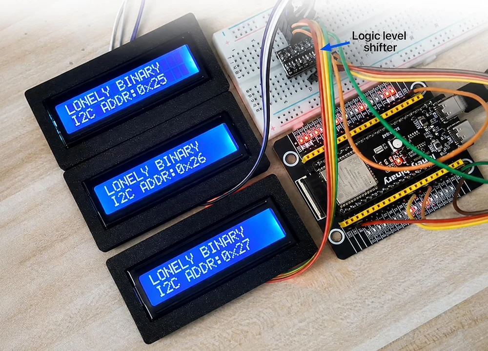
Eight is the ceiling. If you want more than eight character displays on one bus you need a second bus or a multiplexer, and at that point a different kind of display is usually the better answer.
Run the scanner first
The scanner is the cheapest diagnostic on this bench. It asks every address in turn and prints the ones that answer, and an answer proves a lot: the display has power, the two signal wires are the right way round, and the display can pull a line low back through whatever is between you and it.
Anything in 0x20 to 0x27 is a PCF8574, and on this bench that means the display. Anything outside it is something else you have plugged in.
The code
A bus scanner. It prints every address that answers, once every three seconds, and flags anything in the range this display can be. Run it before you suspect your code of anything.
// Wiring (Arduino Uno):
//
//   LCD GND -> GND
//   LCD VCC -> 5V
//   LCD SDA -> A4
//   LCD SCK -> A5
//
// Arduino IDE: Tools > Board "Arduino Uno", Serial Monitor at 9600.
// No library needed — Wire is built in.

#include <Wire.h>

void setup() {
  Serial.begin(9600);
  Wire.begin();
  Wire.setClock(100000);   // the expander is specified to 100 kHz
  Serial.println("scanning");
}

void loop() {
  int found = 0;
  for (uint8_t addr = 1; addr < 127; addr++) {
    Wire.beginTransmission(addr);
    if (Wire.endTransmission() == 0) {
      Serial.print("  0x");
      Serial.print(addr, HEX);
      if (addr >= 0x20 && addr <= 0x27) Serial.print("  <- a PCF8574, so probably the display");
      Serial.println();
      found++;
    }
  }
  if (found == 0) Serial.println("  nothing answered - check VCC, GND, SDA and SCK");
  Serial.println();
  delay(3000);
}
One line and no more means one display. Nothing at all means the wiring, not the address — the scan talks to a chip that is powered and connected, and it cannot fail politely. Two displays both printing 0x27 is two boards fighting over one address, and the pads are the fix.
When it does not work
That is a wiring fault, not an address problem — the scan asks all 126 addresses, so it cannot miss one. Check 5 V on the display's own VCC pin, a shared ground, and that SDA and SCK are not swapped. On a 3.3 V board, check the level converter is powered on both sides.
Then the bus is fine and the contrast is not. Turn the trimmer through its whole travel; “Power, and the contrast trimmer” has the detail. The scan succeeding proves the display can pull a line low, which is most of the wiring.
Both are answering at 0x27 and the scan cannot tell them apart. Bridge one address pad on the second display, rescan, and give each one its own address in your sketch. Until you do, writing to either one writes to both.
0x3F belongs to the PCF8574A, a different part whose base address is 0x38. This board carries the plain PCF8574T, so it can only be 0x20 to 0x27. If nothing in that range answers, the problem is not the address.
That is what the pad does. Bridging pulls that bit low, so the address counts down from 0x27. Re-run the scan and put the new number in the LiquidCrystal_I2C constructor.
The one chapter to read before this display meets an ESP32.
Why it wants five volts →Edit this page — content/books/lcd1602/find-its-address.mdx
Questions about this product
See what other owners have asked, and read their solutions.
3-Pack 1602 LCD Display Module, I2C 16x2 Blue
Loading discussions…
Discuss this article
Ask about this page. The answer stays here, on the page it belongs to, for whoever hits the same wall next.