COMMON to 5 V
Four wires and a rule that reads backwards the first time: writing LOW turns a segment on. It is not a quirk of this part — it is what happens when the microcontroller is the bottom of the circuit rather than the top.
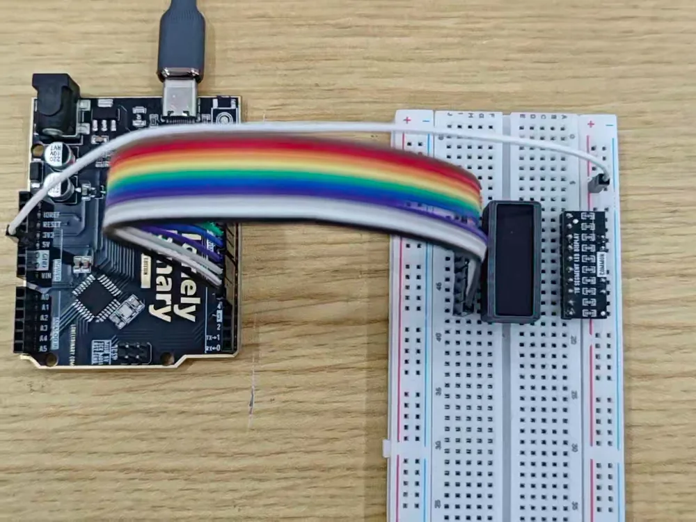
The four connections
- Put the bar across the breadboard's centre channel.
- Wire one row of its pins to the resistor board's TO SEGMENT LED DISPLAY row, segment for segment.
- Wire the resistor board's COMMON row to the Arduino's 5V pin.
- Wire the bar's other row to ten digital pins — D4 to D13 in the sketch that follows.
Why LOW means on
The current comes down from 5 V, through a 220 Ω resistor, through the LED, and
into a GPIO pin. For it to flow, the pin has to be somewhere for it to go —
which means the pin has to hold 0 V. That is what digitalWrite(pin, LOW)
does.
Writing HIGH does not switch the segment off so much as take away the reason for it to be on: the pin drives 5 V, COMMON is at 5 V, and there is no difference across the LED for current to follow. The name for this arrangement is active low, and it is how most LEDs are driven from a microcontroller.
The mistake the label invites
A row of holes marked COMMON on a black board looks like a ground rail. It is not. Wire it to GND and both ends of every segment sit at or below zero volts, nothing lights, and the symptom is indistinguishable from a dead board.
One wire, one meter reading. Black probe on GND, red probe on COMMON: 5 V.
On a 3.3 V board
The GPIO pins only ever sink here, so an ESP32 or a Pico drives this part perfectly well — but COMMON still wants 5 V, not 3V3. Take it from the board's 5V or VIN pin while it is powered over USB. 3.3 V or 5 V is about what happens if you do not.
When it does not work
It should, completely. If a segment glows faintly at HIGH, the pin is not really driving — check that pinMode(pin, OUTPUT) ran for it. A pin left as an input floats, and a floating pin with 5 V on the other side of an LED will let a little through.
Before setup() runs, every pin is an input and every segment should be dark. If they are all on at reset, COMMON is probably wired to a pin rather than to the 5V rail, or the bar is in the wrong way round and you have found the one wiring that lights it by accident. Measure COMMON against GND: it should be 5 V and nothing else.
5V. On an Uno powered over USB they are close, but VIN is the raw input — up to 12 V from a barrel jack — and 12 V through 220 Ω is about 45 mA into a pin that is rated for 40. Use the 5V pin.
Not a separate one. The GPIO pins are the ground end of every segment, so the return path is through the microcontroller itself. If the bar is on a different board from the one driving it, then yes — the two boards must share a ground.
Edit this page — content/books/led-bar-graph/common-to-five-volts.mdx
Questions about this product
See what other owners have asked, and read their solutions.
10-Segment LED Bar Graph Kit, 12 Bars in 6 Colours
Loading discussions…
Discuss this article
Ask about this page. The answer stays here, on the page it belongs to, for whoever hits the same wall next.