The resistor board
Ten 220 Ω resistors from ten holes to one rail, which saves you soldering a hundred and twenty of them across the kit. It arrives with no pins in it, and the row marked COMMON is the positive end of every segment — not a ground.
What is on it
Ten chip resistors, marked 221 — 22 followed by one zero, so 220 Ω. Each one runs from a hole in the row printed TO SEGMENT LED DISPLAY down to a rail that surfaces at the four holes printed COMMON. The two small holes at the ends of that row are not plated; they are for screws.
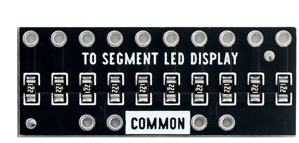
That is the whole circuit. Twelve boards save you soldering a hundred and twenty resistors, which is the entire reason they are in the box.
Why 220 Ω
An LED will take as much current as you let it, and then stop working. The resistor is what decides how much. The LED keeps its own two or three volts whatever happens, so the resistor gets whatever the rail has left, and the current is that voltage divided by the resistance.
Below about 150 Ω one pin is being asked for more than the chip is characterised to sink; above about a kilohm the bar is a night light. 220 Ω is where the board sits, and it is a good default to copy if you ever wire one of these by hand.
The pins it does not come with
The board is bare. There are header strips in the box, and fitting them is the first thing to do:
- Break a ten-way length off a strip.
- Push it through the TO SEGMENT LED DISPLAY row from the printed side, so the long ends stick out of the back.
- Solder all ten from the back.
- Do the same with a two- or four-way piece in the COMMON row.
A joint that is not soldered still touches, most of the time, which is the worst kind of fault to have: it looks like a bug in your sketch. When nothing lights shows what it reads like on a meter.
COMMON is not a ground
The name invites the mistake. This rail is the top of every segment, not the bottom — it goes to 5 V. Wire it to ground and nothing lights at all, whatever the code does, which is the subject of the next page.
When it does not work
That is how it ships. Break a ten-way piece off one of the header strips, push it through the row printed TO SEGMENT LED DISPLAY from the silkscreen side, and solder all ten from the other face. Do two or three of the COMMON holes as well — you only need one electrically, but a board held by one pin pivots in the breadboard.
A header pushed through and not soldered makes contact some of the time, which looks exactly like a software bug. Go over every joint. A good one is a small shiny cone around the pin; a ball sitting on top of the pad has not wetted the hole.
They are not plated, so they are not connected to anything. They are there to screw or glue the board down.
Yes, and 220 Ω is a sensible value to copy. Going much below about 150 Ω asks one pin for more current than the ATmega328P is characterised at, and going much above a kilohm gives you a bar you cannot see on a lit desk.
Yes. Each of the ten segments needs its own resistor — one resistor shared between several segments would make each segment dimmer as more of them lit, which is exactly the effect a bar graph must not have.
Where the rail goes, and why writing LOW is what lights a segment.
COMMON to 5 V →Edit this page — content/books/led-bar-graph/the-resistor-board.mdx
Questions about this product
See what other owners have asked, and read their solutions.
10-Segment LED Bar Graph Kit, 12 Bars in 6 Colours
Loading discussions…
Discuss this article
Ask about this page. The answer stays here, on the page it belongs to, for whoever hits the same wall next.