Specifications
| In the box | 12 bar graphs, 2 each of 6 colours; 12 resistor boards; 12 printed frames; male pin header strips; a storage case |
|---|---|
| Segments | 10 per bar, each an independent LED with its own anode pin and cathode pin. No driver chip, nothing to initialise |
| Package | 20 pins on a 2.54 mm pitch in two rows 7.62 mm apart, so it straddles a breadboard's centre channel. Body 25.4 × 10.1 mm, 14.2 mm tall |
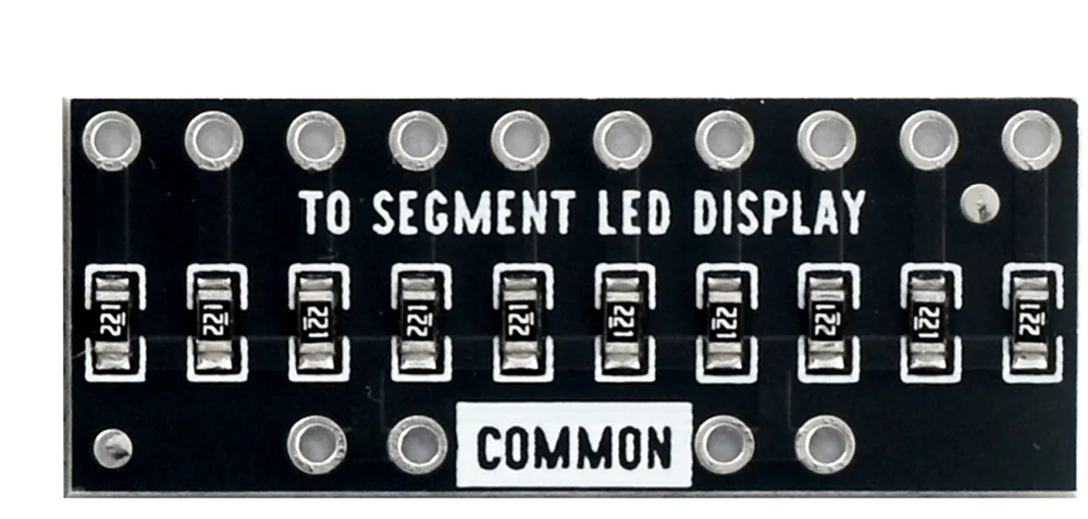
| Resistor board | 10 × 220 Ω chip resistors, marked 221, each from one hole in the TO SEGMENT LED DISPLAY row to the COMMON rail. Ships with no pins fitted |
| Colours | Red, yellow, green, blue, white, and a multicolour bar of 2 red, 3 yellow, 2 green and 3 blue segments |
| Forward voltage | About 2 V for red and yellow, about 3 V for green, blue and white. Typical for the chemistry rather than measured |
| Segment current | About 14 mA for a red or yellow segment and about 9 mA for green, blue or white, from a 5 V rail through the board's 220 Ω |
| Rail | COMMON goes to 5 V, not to ground. The GPIO pins sink the current, so writing LOW lights a segment |
| Pins it needs | 10 digital outputs, one per segment — or 3 through a pair of 74HC595 shift registers |
| On an Arduino Uno | Nine of the ten pins share one 100 mA sink budget in the ATmega328P, and ten red segments at once is about 122 mA of it |
What it is
Ten LEDs in one package, side by side behind a black face, with twenty pins: ten anodes along one edge and ten cathodes along the other. There is no driver chip in it. Each segment is an ordinary two-pin LED that happens to share a piece of plastic with nine others.
That makes it the simplest display you can buy and the most literal: one wire
per segment, one digitalWrite per segment, and nothing in between to
misconfigure.

What is in the box
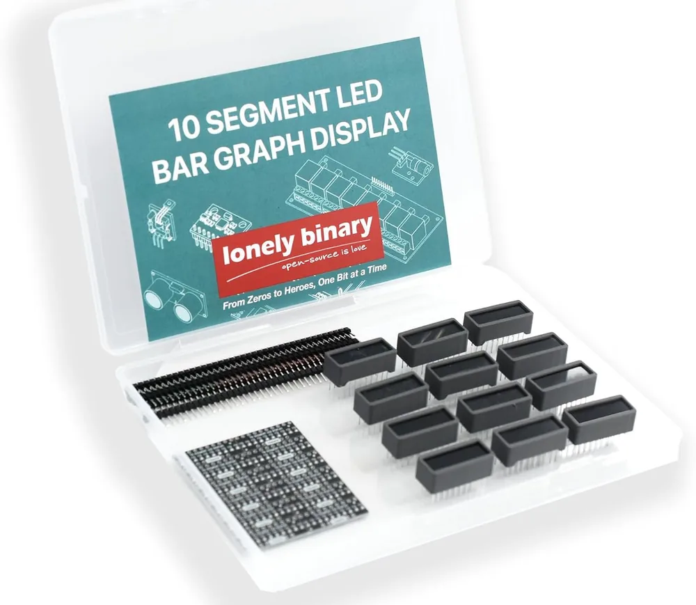
Twelve bars — two each of red, yellow, green, blue, white and multicolour — twelve current-limiting resistor boards, twelve printed frames, strips of male pin header for the boards, and a case.
The resistor board
Ten chip resistors marked 221 — 220 Ω — each running from one hole in the row printed TO SEGMENT LED DISPLAY down to a rail that surfaces at four holes printed COMMON. That is the entire circuit, and twelve of them save you soldering a hundred and twenty resistors.
Which colour for which rail
| Rail on COMMON | Red, yellow | Green, blue, white |
|---|---|---|
| 5 V | about 14 mA, bright | about 9 mA, bright |
| 3.3 V | about 6 mA, readable | a milliamp or two, very dim |
| 3 V cell | about 4 mA, dim | does not light |
The LED takes its own forward voltage before the resistor gets any say, so dropping the rail hurts the 3 V colours far more than the 2 V ones. 3.3 V or 5 V works it out.
Wiring, in four lines
- Put the bar across the breadboard's centre channel.
- One row of its pins to the resistor board's TO SEGMENT LED DISPLAY row, segment for segment.
- The board's COMMON row to 5V.
- The bar's other row to ten digital pins — D4 to D13 in the handbook's sketches.
No ground wire to the bar: the GPIO pins are the ground end of every segment. If the bar stays dark, turn it end for end — one row is the anodes and nothing printed on the part says which.
Where to start
The handbook below is eleven short articles with a working figure in each. If you only read one, read COMMON to 5 V, which is the wiring and the reason LOW means on. If it is already wired and dark, when nothing lights separates the four faults that all look identical.
When it doesn’t work
- Which row of pins is the anode row?
- Nothing printed on the part tells you, and the part number on the body is not a reliable guide — the product renders reuse one number across several colours. You find out by trying it: wire it up, run the sketch, and if the bar stays dark, lift it out and turn it end for end. With the kit's 220 Ω resistor board in the circuit there is nothing that can be damaged by having it the wrong way round — an LED simply does not conduct backwards, so no current flows at all.
- Why does writing LOW turn a segment on?
- Because the microcontroller is the bottom of the circuit, not the top. Current comes down from 5 V through the 220 Ω and the LED into a GPIO pin, and it only flows if that pin is holding 0 V. Writing HIGH does not switch the segment off so much as remove the difference across it: the pin drives 5 V, COMMON is at 5 V, and there is nothing left to push. The arrangement is called active low, and it is how most LEDs are driven from a microcontroller.
- The resistor boards have no pins on them.
- That is how they ship, and the header strips in the box are what go in them. Break a ten-way piece off a strip, push it through the row printed TO SEGMENT LED DISPLAY from the printed side, and solder all ten from the back; then do two or four of the COMMON holes so the board does not pivot in the breadboard. A header that is pushed through and not soldered makes contact some of the time, which looks exactly like a bug in your sketch.
- Can I run it from an ESP32 or a Pico?
- Yes, and the GPIO pins are not the problem — they only ever sink current here. What matters is where COMMON goes. On a 3.3 V rail there is almost nothing left after a green, blue or white LED's own 3 V, so those bars barely light; take COMMON from the board's 5V or VIN pin instead. Red and yellow bars work acceptably straight off 3.3 V at about 6 mA a segment.
- Why is my blue bar dimmer than my red one?
- Forward voltage, and the code has nothing to do with it. A red LED keeps about 2 V for itself and a blue one about 3 V, so behind the same 220 Ω on the same 5 V rail the red segment gets about 14 mA and the blue about 9 mA. On the multicolour bar both kinds are in the same package, which is why its blue end looks softer than its red end.
- Is it a problem to light all ten segments at once?
- On an Arduino Uno, slightly. The ATmega328P's data sheet budgets sink current by port group rather than by pin, and nine of the demo sketch's ten pins are in the same group — ports B0 to B5 and D5 to D7 — whose sum should stay under 100 mA. Nine red segments at 14 mA is about 122 mA. Nothing is damaged; what the data sheet stops promising is that a pin still holds a proper LOW, so the bar dims slightly and unevenly. Light fewer at once, use one of the 3 V colours, or drive it through a shift register.
- Do I need a ground wire to the bar?
- Not a separate one, if the same board drives it: the GPIO pins are the ground end of every segment, so the return path is through the microcontroller. If the bar and the driving board have different power supplies, then yes — they must share a ground.
- How many pins does it cost?
- Ten, one per segment, wired straight. That is fine for one bar and leaves eight of an Uno's eighteen usable pins. Two bars does not fit, and the usual answer is a 74HC595 shift register — three wires for as many bars as you like, with the LED current coming off the register's supply rather than the microcontroller's port group.