Logic 2
Saleae's application finds this analyzer with no setup at all, which makes it the right one to see your first capture in. It will also print a pulse width to the nanosecond, and the hardware cannot support the last digit of it.
Why start here
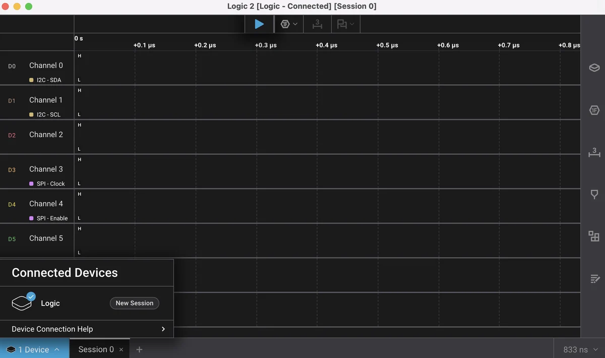
Because there is nothing to configure. This analyzer identifies itself to a host
the way the original Saleae Logic did, so Logic 2 finds it, lists it as
Logic, and hands you a working capture window without a driver dialog, a
device scan or a decision about which of two things to install.
For a first capture that matters more than any feature comparison.
Installing it
Download it from Saleae's own site and install it the way the platform expects: run the installer on Windows, drag it to Applications on macOS, run the AppImage or the package on Linux. The Windows installer sets up its own USB driver as it goes, which is the only platform where anything is installed besides the application.
Then plug the analyzer in — either cable, a port on the machine rather than a hub — and open it. The device should be in the panel before you have finished looking for it.
The first capture
Four decisions, in this order.
Ground. Not a setting; a wire. Fit it before anything else — and here is why.
Which channels. Clip two or three, and turn the rest off so the screen is readable. Turning them off saves no bandwidth at all, but eight empty rows make the two that matter harder to find.
The sample rate. Pick it from the bus rather than from the top of the list. Samples per bit is the arithmetic; for a 400 kHz I²C bus, a few megasamples a second is ten times what the decoder needs and a fraction of the USB load.
How long. Capture around the event rather than for a minute. If your firmware reads a sensor every second, a capture of a few hundred milliseconds started at the right moment has everything in it.
Then press the green button, make the board do the thing, and stop.
Adding a decoder
Logic 2 calls them analyzers, and one is added from the panel on the right: pick the protocol, tell it which channel is which signal, and a row appears under the traces with the decoded traffic on it.
That channel assignment is the setting that goes wrong, and it goes wrong quietly — a decoder handed the wrong two channels produces output rather than an error. When the decode is wrong is the chapter on recognising it.
The measurement, and what it is worth
Sooner or later you will drag across two edges to measure something, and Logic 2 will give you a number with more precision in it than the hardware has.
Everything in a capture is on the sample grid. An edge recorded at tick N happened somewhere between tick N−1 and tick N, so a width measured between two edges carries that uncertainty twice — about 83 ns at the top rate, and proportionally more at any lower one.
This matters at exactly the moment people reach for it: checking a pulse against a datasheet minimum. If the measurement lands within a tick or two of the limit, the honest answer is that the instrument does not know. That is not a disappointing result, it is a result — and it tells you to reach for an oscilloscope rather than to conclude anything about the part.
The thing worth knowing about the pairing
Logic 2 works here because of a compatibility that belongs to somebody else's product line. That is a real and pleasant convenience, and it is not a promise anyone made to us.
So use it, and know that PulseView reaches the same hardware through an open-source driver that nobody can withdraw. It is worth having both installed before you need the second one.
When it does not work
Work the chain in order, cheapest first: swap to the other cable in the box, move to a port directly on the machine rather than a hub, then look at the driver. On Windows the installer sets one up and it can be displaced by a previous Zadig run for PulseView. See when the device is not there for the whole walk.
Usually the sample rate against the USB bus rather than anything about the trigger. Drop the rate, move off the hub, and close whatever else is streaming from the same controller — the serial monitor on the target board is the usual culprit.
The analyzer has been pointed at channels with nothing on them. Check the channel numbers in its settings against what is physically clipped where, and remember that on the expansion board the clip pads run CLK, GND, 7, 5, 3, 1, 6, 4, 2, 0 rather than in numerical order.
It will, and neither is wrong. Every edge in a capture is recorded on the sample grid, so at 24 MS/s a width is a count of 41.7 ns ticks and carries about two ticks of uncertainty. A measurement within a tick or two of a datasheet limit is a question this instrument cannot answer, not a pass or a failure.
The open-source one, its driver, the macOS warning that stops it opening, and the decoders that stack on each other.
PulseView →Edit this page — content/books/logic-analyzer/logic-2.mdx
Questions about this product
See what other owners have asked, and read their solutions.
Logic Analyzer Kit, 8-Channel 24 MHz
Loading discussions…
Discuss this article
Ask about this page. The answer stays here, on the page it belongs to, for whoever hits the same wall next.