The kit in front of you
Ten signals leave the analyzer on one connector, and the two breakout boards present them three different ways. One of the three does not run in channel order, which is worth finding out now rather than through a decode that quietly reports the wrong address.
Ten signals, one connector
Eight channels, an external clock input and a ground, on a single 2×5 header at the end of the case. The lid prints the map, and it prints it in pairs because the connector is five rows of two:
| CH0 | CH1 |
| CH2 | CH3 |
| CH4 | CH5 |
| CH6 | CH7 |
| CLK | GND |
Counting along the connector as though it were a run of ten is the mistake that transposes every channel before anything is plugged in. Read the label.
CLK is an input for an external sample clock and does nothing on an ordinary
capture, so on most benches this row is one pin you must fit and one you can
ignore. Which pin you must fit is the subject of its own
chapter.
Three layouts, the same ten signals
The expansion board mates with the header and re-presents everything twice over. Down one edge is a 2.54 mm strip with two holes per signal, so a channel can go to a pin header and to a soldered wire at the same time. Down the other edge are ten oversized plated pads, sized for the jaws of an alligator clip.
Those pads are the part worth reading twice. They run CLK, GND, 7, 5, 3, 1, 6, 4, 2, 0 — the odd channels and then the even ones. That is a perfectly ordinary routing decision and a trap if you assume the edge matches the strip on the other side of the same board.
The breadboard adapter answers a different question. It turns the connector through a right angle into two rows of ten, each row running GND, CLK, 7, 6, 5, 4, 3, 2, 1, 0, so the analyzer hangs off the end of a breadboard instead of lying across the middle of it, and every channel has a tie point on both sides.
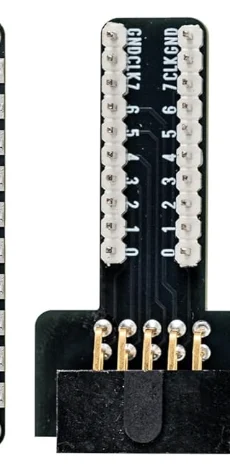
The cables
Two, both micro-USB at the analyzer end, differing only at the host end: one ends in USB-A, the other in USB-C. There is no functional difference and no reason to prefer one — take whichever fits the machine.
Keep them. A micro-USB cable out of a drawer is a coin flip between a data cable and a charge-only one, they are indistinguishable from the outside, and a charge-only cable produces exactly the symptom that sends people to reinstall their software.
The clips
Ten hook clips and five alligator clips, plus a ribbon of jumper wires. The hooks are sized for header pins and through-hole leads; the alligators are for anything with a tab or a wire end.
Where each of those stops working is its own chapter, and the short version is that the jaw does not get smaller because the component did.
When it does not work
The connector is five rows of two, not a run of ten. Counting along it pairs CH0 with CH2 and puts everything one position out. Read the map on the lid instead — CH0 is opposite CH1, CH2 opposite CH3, and the last row is CLK opposite GND.
They are in a different order, and both are correct. The 2.54 mm strip runs 0 to 7 then CLK and GND. The clip pads down the other edge run CLK, GND, then the odd channels 7, 5, 3, 1, then the even ones 6, 4, 2, 0. Read the silkscreen at the pad you are using, every time.
Both cables in the box carry data, but every drawer also contains a charge-only micro-USB that looks identical from the outside. Try the other cable in the box before anything else — it is the cheapest link in the chain to eliminate and the one most often at fault.
Either. The two rows carry the same ten signals, each running GND, CLK, 7, 6, 5, 4, 3, 2, 1, 0, so every channel has a tie point on both sides of the board. Use whichever side your jumpers reach.
One division decides whether this instrument can see your bus at all, and it is the division nobody does before buying.
Samples per bit →Edit this page — content/books/logic-analyzer/the-kit-in-front-of-you.mdx
Questions about this product
See what other owners have asked, and read their solutions.
Logic Analyzer Kit, 8-Channel 24 MHz
Loading discussions…
Discuss this article
Ask about this page. The answer stays here, on the page it belongs to, for whoever hits the same wall next.