Specifications
| Channels | 8, plus an external clock input and a ground |
|---|---|
| Sample rate | Up to 24 MS/s, selected in software |
| Time resolution | 41.7 ns at the top rate — one sample interval |
| What is stored | One bit per channel per sample. No voltage, no analogue |
| Capture memory | None worth the name. Samples stream over USB as they are taken |
| Connector | One 2×5 0.1 in header — CH0/CH1 through CH6/CH7, then CLK and GND |
| Host port | Micro-USB. A micro-to-A and a micro-to-C cable are in the box |
| Software | Saleae Logic 2, or PulseView through sigrok's fx2lafw driver |
| Platforms | Windows, macOS and Linux, for both applications |
What it is
Eight wires in, one bit per wire per sample, straight up a USB cable to a program that turns the edges back into bytes. That is the whole instrument, and both halves of that sentence matter: the eight channels are why it is useful, and the one bit is why it is not an oscilloscope.
It does not record voltage. Each channel is compared against a fixed threshold and stored as a 1 or a 0, so a ringing edge that never crosses back is recorded as a clean edge, and a rail that has sagged to 1.6 V is recorded as a flat zero forever. What you get instead is eight signals at once, for as long as you care to run, with a decoder on top — which is the right trade for almost every question a microcontroller raises and the wrong one for every question about signal integrity.
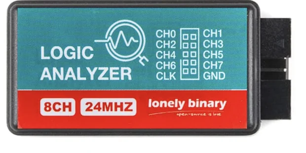
What is in the box
The analyzer, two breakout boards, two cables, fifteen clips and a ribbon of jumper wires, in a case that closes.
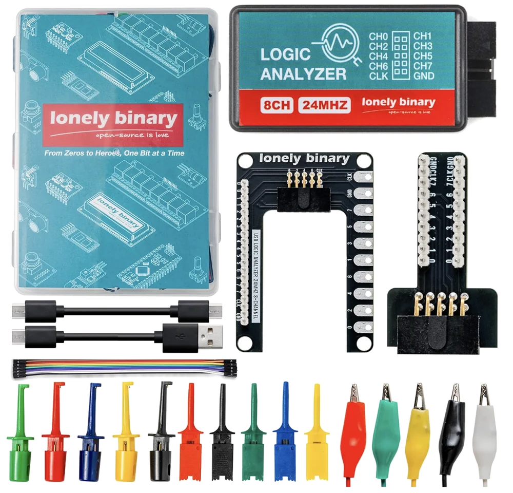
The three boards
The analyzer brings all ten signals out on one 2×5 header, and the two breakout boards are two different answers to what to do with it.
| Board | What it gives you |
|---|---|
| The analyzer | The 2×5 header, and the channel map printed on the lid |
| Expansion board | The same ten signals on a 2.54 mm strip, two holes each, plus ten oversized pads sized for an alligator clip |
| Breadboard adapter | The same ten again, turned through a right angle into two rows of ten so the analyzer hangs off the end of a breadboard rather than lying across it |
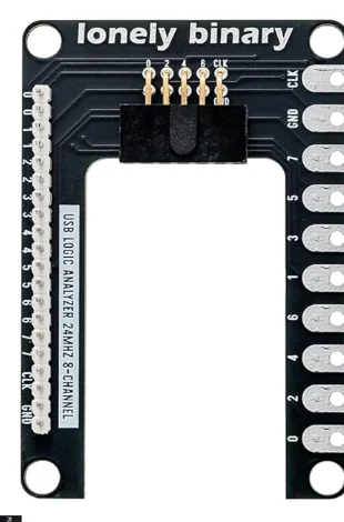
The breadboard adapter carries the same ten signals twice over, each row running GND, CLK, 7, 6, 5, 4, 3, 2, 1, 0, so every channel has a tie point on both sides of the board. The kit in front of you has the three layouts side by side, with the same signal lit in all of them.
What it can decode
The sample rate is the specification. Everything else about whether this instrument can see your bus is one division: 24 MS/s divided by the bit rate is how many samples land inside each bit, and below about four of them a decoder is guessing.
| Bus | Samples per bit at 24 MS/s | |
|---|---|---|
| UART, 115200 baud | 208 | comfortable |
| I²C, 100 kHz | 240 | comfortable |
| I²C, 400 kHz | 60 | comfortable |
| WS2812, 800 kHz | 30 | comfortable |
| SPI, 1 MHz | 24 | comfortable |
| SPI, 4 MHz | 6 | marginal |
| SPI, 8 MHz | 3 | do not trust it |
| QSPI flash, 40 MHz | 0.6 | out of reach |
Which is to say it decodes everything a beginner's board actually does, and stops at the buses a microcontroller uses to talk to its own flash. Samples per bit works the arithmetic through and is the page to read before deciding the hardware is faulty.
The software
Two applications, both free, both on Windows, macOS and Linux, and the device answers to either.
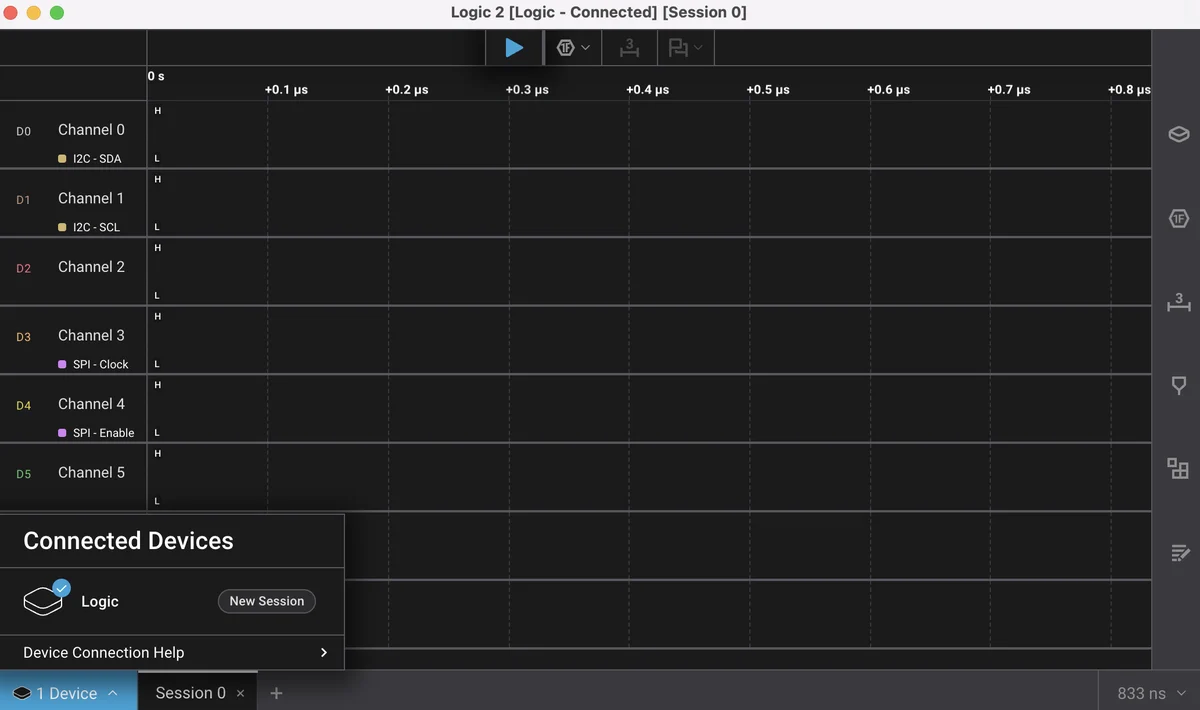
Logic 2, from Saleae, is the friendlier one and the one to start with. This
analyzer presents itself to a host the way the original Saleae Logic did, so
Logic 2 finds it, calls it Logic, and gives you its analyzers and its
timing tools without any setup at all.
PulseView, from the sigrok project, is the open-source one. It reaches the
device through sigrok's fx2lafw driver and lists it as Saleae Logic with 8
channels, and it carries well over a hundred protocol decoders that stack on
each other.
The honest note about the pair: Logic 2 works because of a compatibility that belongs to somebody else's product, and PulseView works because of a driver that is ours to keep. Start with Logic 2 if you have never seen a capture before, and know where PulseView is.
Ground first
One wire matters more than the other eight. The analyzer compares each channel against its own ground pin, so that pin has to be on the same copper as the circuit. Without it the threshold is crossed by whatever the two power supplies are doing relative to each other, and the result is not silence — it is a capture full of edges, and a decoder that finds occasional plausible bytes in them.
If a trace is dense with transitions you cannot account for, check the ground wire before you read another line of firmware. Ground first is the chapter on why it fails in the direction it does.
Where to start
The handbook below is the walk. If you want one page rather than eleven, what it actually records is the one that changes how you read every capture afterwards, and your first I²C capture is the one that gets a sensor on screen.
When it doesn’t work
- The capture is a wall of edges that match nothing my board is sending.
- The ground wire is missing. The analyzer decides high or low by comparing each channel against its own ground pin, so if that pin is not on the same copper as the circuit, the threshold gets crossed by the difference between two power supplies rather than by your data. It does not fail quietly: you get a busy, plausible trace and a decoder that finds occasional real-looking bytes in it. Fit the ground wire before any channel, even when you are probing one signal.
- The decoder reports an address, but it is not my device's address.
- SDA and SCL are almost certainly the wrong way round in the decoder settings, not on the board. Nothing warns you — the decoder finds edges either way, groups them, and reports an address that is in range. Look at the row you called the clock: a real SCL is an even run of pulses, and a clock that sits still for three bit times is a data line. Swap the two channel numbers before you touch the wiring.
- My SPI bus decodes intermittently, or not at all.
- Divide 24 MS/s by the bus clock. At 1 MHz that is 24 samples a bit and it is fine; at 8 MHz it is three, which is the band where a capture looks plausible and a decode is luck. Below about four samples a bit the decoder is not producing a degraded version of the traffic, it is producing noise with a plausible shape. Halve the SPI clock in your sketch for the duration of the debugging session — it is the fastest fix there is.
- The capture has a gap in it, or the software says samples were dropped.
- There is no capture memory on the device: at 24 MS/s it is sending 24 MB/s continuously up the USB cable, and it shares that bus with the board you are debugging, the serial monitor watching it and everything else on the same controller. Drop to the lowest rate your slowest signal can live with, put the analyzer on its own port rather than through a hub, and keep it off the controller the target board is on.
- The operating system sees a device but the application does not.
- That is the driver, and it is the only part of this with a different answer per platform. On Windows, Logic 2 installs its own and PulseView wants WinUSB installed with Zadig — setting one up takes the device away from the other, and going back means running Zadig again. On macOS and Linux neither application needs a driver; on Linux it needs permission instead, which is a udev rule rather than running the application as root. Also check nothing else already has the device open, because the second application to ask gets an empty device list rather than an error.
- Can I probe a 5 V Arduino, or 1.8 V logic?
- The kit is sold for microcontroller work and that is what it is good for. There is no adjustable threshold and no level shifting on any of the three boards, so a signal either crosses the fixed threshold or it does not, and 1.8 V logic is the case to test before you trust a capture rather than after. Keep motor supplies, unregulated rails and anything above 5 V off the channels entirely — a logic analyzer has no protection worth relying on, and this is the one mistake that ends with a new analyzer.