Specifications
| Display | 8 x 8 pixels, 64 LEDs in one package, a single fixed colour per board. The TK52's is a red 1088AS, 32 mm square |
|---|---|
| Driver | One MAX7219 (HGSEMI MAX7219M on the TK52). It holds the picture in eight registers of its own and scans it, so your board sends a frame and then has nothing more to do |
| Boards | Two. The TK52 has one 6-pin header and no DOUT: the chip's DOUT pin reaches no pad. The chainable module has six pads at each of two opposite edges, marked IN and OUT |
| Header | TK52: 6-pin right-angle male, 2.54 mm pitch, fitted, GND VCC CS DIN NC CLK from the left with the matrix up. No square pad: count from GND. NC is connected to nothing. The 3-pack's headers come loose |
| Signal wires | 3 — DIN, CLK and CS. A chain of 3-pack modules stays at 3; two TK52s need a CS each, 4 wires |
| Supply voltage | 5 V. The MAX7219's operating range is 4.0 to 5.5 V, so 3.3 V is outside it |
| Logic level | A HIGH must reach 3.5 V. A 5 V board clears it; a 3.3 V board is below the datasheet minimum and usually works anyway |
| Brightness | 16 levels, set in software. A duty cycle from 1/32 to 31/32 at a fixed current, not a change in LED current |
| LED current | TK52: R7, 10 kΩ from VCC to ISET, sets about 40 mA per LED while lit, the chip's ceiling. Each column is lit at most an eighth of the time |
| Scan rate | 800 Hz typical with all eight columns scanned, 500 to 1300 Hz specified |
| Clock | 10 MHz maximum, which is a 100 ns minimum clock period |
| Current | 330 mA typical with every LED lit at full brightness, 150 µA in shutdown. Tens of milliamps for an icon at a normal setting |
| TK52 board | 32 × 41 mm, two 4.8 mm mounting holes 24 mm apart below the header. The chip, R7 and a 100 nF capacitor sit under the matrix |
| In the box | The 3-pack holds 3 modules, one each in red, green and blue, with a colour-matched case and a set of headers for each. The TK52 ships singly, header fitted, and in the TinkerBlock kits |
| Module size | 3.2 x 3.2 x 1.0 cm for the chainable module, measured without its case |
What it is
Sixty-four LEDs and a driver that scans them fast enough to look continuous. You send eight bytes, one per column, and the chip holds the picture: send a frame, stop talking, and it stays.
The driver is a MAX7219. It does the multiplexing, the constant-current drive and the brightness, and it takes its instructions as sixteen-bit messages on three wires: data, clock and chip select. It wants 5 V on VCC; its signals want a HIGH of 3.5 V, which a 3.3 V board misses by two tenths and usually gets away with.
Two boards, one chip
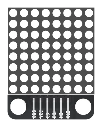
The TK52 is the TinkerBlock block. The matrix covers the top of a 32 × 41 mm board, a six-pin right-angle header sits along the bottom, fitted, and the back reads TK52 MATRIX LED. The chip's DOUT pin reaches no pad, so a TK52 talks to your board and to nothing else.
The chainable module comes three to a box, in red, green and blue. It is a 3.2 cm square with six pads at each of two opposite edges: IN carries DIN, OUT carries DOUT, and the other five pads are the same on both edges.
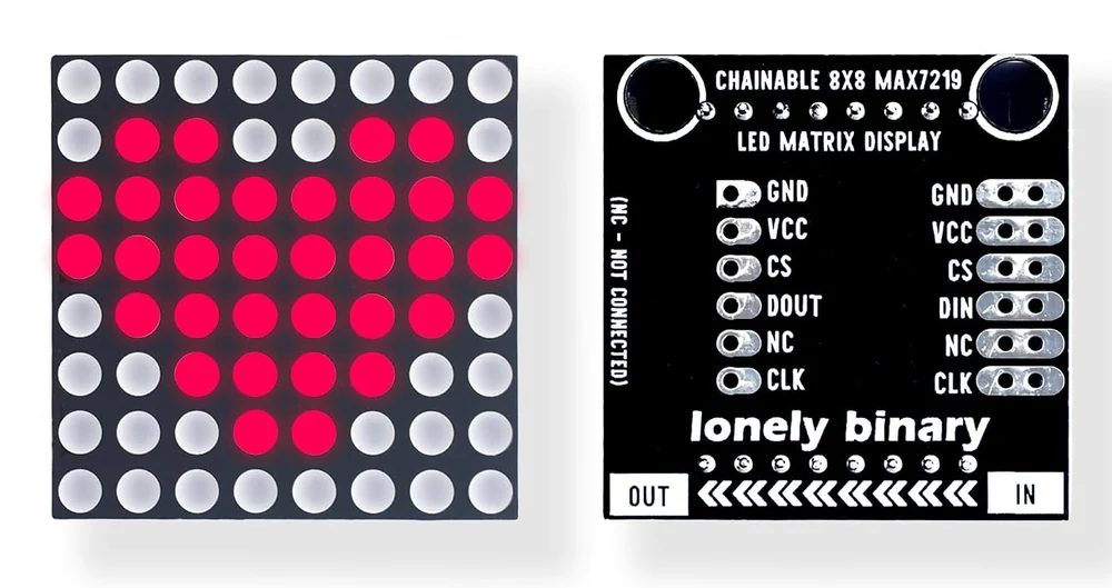
| TK52 | Chainable module (3-pack) | |
|---|---|---|
| Header | 6 pins, fitted | 6 pads each edge, headers loose |
| DOUT | none | on the OUT edge |
| More than one | a CS wire each | DOUT to DIN, three wires in all |
Wiring the TK52, in five lines
Matrix up, header at the bottom, from the left:
- GND to your board's GND. There is no square pad; GND is printed.
- VCC to 5V (VBUS on a Pico). Never 3V3.
- CS to D10 on an Uno, GPIO 5 on an ESP32, GPIO 10 on an ESP32-S3, GP17 on a Pico.
- DIN to D11, GPIO 23, GPIO 11 or GP19.
- CLK to D13, GPIO 18, GPIO 12 or GP18. NC, between DIN and CLK, stays empty.
Chaining the 3-pack modules
Chaining is serial. DOUT of one module goes to DIN of the next, while VCC, GND, CLK and CS run straight through. Each chip passes on what it received 16.5 clock cycles later, so the message sent first travels furthest. The 3-pack ships its headers loose: joining two modules is a soldering job, and past two on one jumper, run 5 V and ground to each board from the supply.
Where to start
The handbook below is ten short articles about the TK52. The six pins and 5 V on VCC, 3.5 V for a HIGH are the ones to read before wiring. One column at a time and Eight bytes for sixty-four LEDs are how the picture gets onto the matrix, and The first picture is the sketch, with no library, for an Uno, an ESP32, an ESP32-S3 or a Pico, in Arduino and in MicroPython. For a chain of four, the 32×8 matrix handbook covers the same chip.
When it doesn’t work
- The display is very dim, or shows nothing at all.
- VCC is not on 5 V. The MAX7219 has one supply pin and its operating range starts at 4.0 V, so a board fed from 3V3 is running under-volted rather than running dim. Move VCC to the 5V pin (VBUS on a Pico) and leave GND where it is.
- Can I run it from 3.3 V?
- Not the supply — 4.0 V is the datasheet minimum. The signals are a separate question: a HIGH has to reach 3.5 V, which a 3.3 V board misses by two tenths of a volt. Driving one of these from an ESP32 or a Pico is common and usually works, and it is out of specification. If it shows garbage, shorten the wires or put a level shifter in DIN, CLK and CS.
- Which pin is GND on the TK52? There is no square pad.
- The left-hand pin, with the matrix up and the header at the bottom: GND, VCC, CS, DIN, NC, CLK. All six pads are the same oval, so the printed name is the mark. NC, between DIN and CLK, is connected to nothing.
- Can I chain the TK52?
- Not board to board. The chip's DOUT pin reaches no pad, so there is nothing to carry data on. Two TK52s can share DIN and CLK with a CS pin each. The chainable module in the 3-pack is the one with an OUT edge.
- Chained modules show the same thing.
- The chain is serial, not parallel. DOUT of one module goes to DIN of the next; wiring both DIN pads to the same pin with one CS gives every chip the same bits. Follow the arrows on the back, which run from IN towards OUT.
- The image is rotated or mirrored.
- Boards differ in how the matrix is mounted on the driver, and the chip cannot tell. On the TK52 the handbook's sketch has a TURN and a FLIP setting; with a library, set the hardware type — MD_MAX72XX::FC16_HW and friends — until it lands the right way up. A display that is lit and responsive but turned already has its wiring right.
- Nothing lights, and the sketch runs.
- A MAX7219 powers up in shutdown mode with its display blanked, drawing about 150 µA. Every sketch has to write 1 to register 0x0C to wake it — lc.shutdown(0, false) in LedControl — and a chip nobody has woken stays dark and looks broken.
- Do the three modules in the 3-pack do different things?
- No. They differ only in LED colour — one red, one green, one blue. Each module is a single fixed colour, not an RGB display. The pinout and the code are the same for all three.