Two ways out, one pair of nets
Four holes at the output end, and only two nets. The screw terminal and the breadboard pins are alternatives on the same copper, 1.8 mm apart, and the terminal sits on top of the pins.
Four holes, two nets
The output end has two pairs of plated holes, and the pairs overlap into a figure-of-eight pad. That is easiest to see on a board with the terminal off:
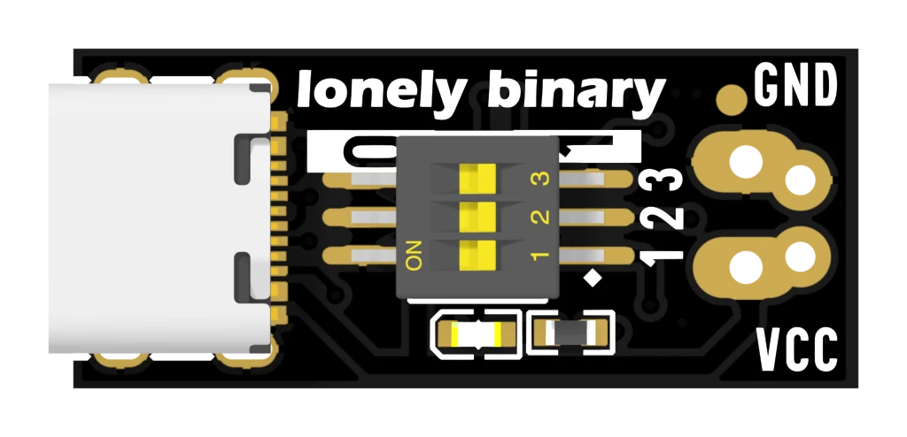
The larger pair is 1.1 mm across and 3.5 mm apart — that is the screw terminal's footprint. The smaller pair is 1.0 mm across and 2.54 mm apart, which is the standard breadboard pitch. They are 1.798 mm apart along the board and joined by copper, so they are the same two connections offered twice, not two separate outputs.
You get one of them
The terminal block's body runs from roughly 19.0 mm to 25.5 mm along the board. The header holes are at 24.15 mm. So the terminal stands over the holes you would want to put pins in, and the choice is made for you unless you are willing to desolder a part that is already fitted.
For nearly everything, the terminal is the better end of that bargain: it takes bare wire up to about 1.5 mm², it needs no soldering, and it holds against a tug. The pins are worth the trouble only when the board has to plug into a breadboard alongside the rest of a circuit.
Or use neither
The holes do not need a connector in them. For a build that will be screwed into a box and left there, tin a length of wire and solder it straight through the terminal pair — 1.1 mm takes up to about 18 AWG comfortably, which is more copper than most of these boards will ever be asked to carry.
Whichever way the wire leaves, check the polarity before the charger goes in. VCC on this board can be 20 V, and there is nothing on it to stop a reversed connection reaching your circuit.
When it does not work
The lower one, marked VCC. GND is the upper one, nearer the GND lettering and the top edge of the board. Both faces of the board print the same two labels in the same place, so you can check from whichever side is facing you.
No. The terminal's plastic body runs from about 19.0 to 25.5 mm along the board and the header holes are at 24.15 mm, so the body stands directly over them. You would have to remove the terminal first, which on a two-pin through-hole part means heating both joints at once or cutting the body away.
Check the two joints on the underside before blaming the part. A terminal that is only held by its plastic has a lifted pad or a dry joint underneath, and it will fail with current flowing through it. Reflow both pins with a little fresh solder.
The one indicator on the board, and why it looks identical whether the charger agreed to 20 V or refused.
The LED says power, not success →Edit this page — content/books/pd-trigger/two-ways-out.mdx
Questions about this product
See what other owners have asked, and read their solutions.
USB-C PD Trigger, 100 W Decoy 5–20 V, 12-Pack
Loading discussions…
Discuss this article
Ask about this page. The answer stays here, on the page it belongs to, for whoever hits the same wall next.