What is in the box
Twelve identical boards, each 26.1 × 11.5 mm with its screw terminal already fitted, and four forty-pin header strips you will barely touch.
What the bag holds
- 12 trigger boards, each 26.1 × 11.5 mm, with the USB-C socket, the chip, the three-way switch and the green screw terminal already soldered on.
- 2 × 40-pin straight breakaway male header strips.
- 2 × 40-pin right-angle breakaway male header strips.
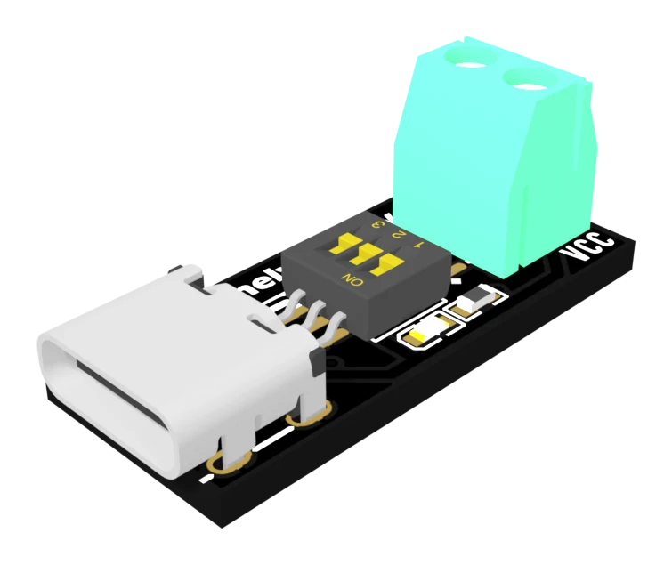
The boards are finished in ENIG — immersion gold — so the pads are gold coloured rather than the dull grey of a cheaper finish. On a board this small, with a connector that gets pushed and pulled, that is worth having.
The header arithmetic
Two holes a board. Twelve boards. Twenty-four pins, out of a hundred and sixty in the bag.
So there is nothing to ration, and nothing to plan. Break pins off in pairs with a pair of pliers, and use the right-angle strips on any board that has to lie flat against a surface.
There is a catch, and it is the subject of two ways out: the header holes are underneath the screw terminal. Fitting pins to a board means taking its terminal off first. Most people never do — the terminal is the easier connection — which is why the strips will probably outlive the boards.
What is not in the box
No cable and no charger. You need a USB-C lead and a supply that does Power Delivery, and which supply you have decides most of what this board can do for you. If you only have an old 5 V brick, start by reading what the charger must offer before you wire anything up.
When it does not work
Because the strips are a stock item and come in forties. Each board has two holes, so twelve boards want twenty-four pins out of the hundred and sixty in the bag. The strips are there so you can put pins on the boards you want on a breadboard, not because you are expected to use them all.
Yes. There is one design in the bag, twelve times, and the back of every one carries the same revision marking and the same voltage table. Nothing needs sorting and no board is set up differently from the others out of the bag.
Do not assume so. The levers hold whatever position they were knocked into, and a board that reads 5 V is indistinguishable from one that reads 20 V until you look at them. Read the levers on each board before you use it — the article on the three switches shows how.
A socket, a chip you cannot see, three levers and two ways out — in the order they sit on the board.
The board, end to end →Edit this page — content/books/pd-trigger/whats-in-the-box.mdx
Questions about this product
See what other owners have asked, and read their solutions.
USB-C PD Trigger, 100 W Decoy 5–20 V, 12-Pack
Loading discussions…
Discuss this article
Ask about this page. The answer stays here, on the page it belongs to, for whoever hits the same wall next.