Specifications
| In the box | 12 trigger boards with screw terminals fitted, plus 2 × 40-pin straight and 2 × 40-pin right-angle breakaway male header strips. 160 header pins against the 24 that twelve boards can take |
|---|---|
| Voltages | Fixed 5, 9, 12, 15 or 20 V, selected by a three-position DIP switch. Which one you get also depends on the charger offering it |
| Chip | WCH CH224K, a USB Power Delivery 3.0 sink controller in a ten-pin ESSOP package on the underside. I/O level configuration, no firmware and nothing to program |
| Ceiling | 100 W, which is 20 V at 5 A. It needs a 100 W charger and an electronically marked cable; an ordinary cable is limited to 3 A, so 20 V tops out at 60 W |
| Setting the voltage | Levers 1, 2 and 3 drive CFG1, CFG2 and CFG3. The bar behind them prints 0 at one end and 1 at the other: 5 V is 1XX, 9 V is 000, 12 V is 001, 15 V is 011 and 20 V is 010. The same table is on the back of the board |
| Output | VCC and GND, brought out twice on the same copper — a 3.5 mm screw terminal (1.1 mm holes) and a 2.54 mm header pair (1.0 mm holes) 1.8 mm behind it. GND is the hole nearer the top edge |
| Power LED | Red, through 5.1 kΩ from the chip's own 3.3 V rail. About 0.3 mA. It proves the board has VBUS, and says nothing about whether the negotiation succeeded |
| Protection | The chip has over-voltage and over-temperature protection for itself, with the over-temperature threshold around 105 °C. There is no fuse, no polyfuse and no TVS on the board — a fault downstream sees whatever the charger will deliver |
| Board | 26.1 × 11.5 mm and 1.6 mm thick, ENIG gold finish, revision V1.2. The USB-C socket overhangs the edge by about 0.7 mm |
What it does
A modern USB-C charger contains four or five separate voltage rails and hands you the lowest one. It stays at 5 V until something on the other end of the cable asks for more, in a protocol called USB Power Delivery, over a wire called CC.
This board does the asking. A CH224K sink controller reads three switch levers, requests the matching voltage, and holds it at a screw terminal — turning a laptop charger into a fixed 5, 9, 12, 15 or 20 V supply for whatever you are building.
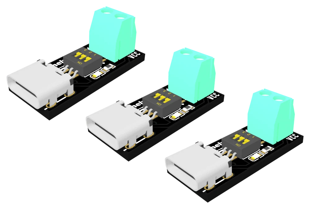
Setting the voltage
The three levers drive the chip's CFG1, CFG2 and CFG3 pins. The bar printed behind them says 0 at one end and 1 at the other, and the same table is on the underside of every board:
| Voltage | Lever 1 | Lever 2 | Lever 3 |
|---|---|---|---|
| 5 V | 1 | X | X |
| 9 V | 0 | 0 | 0 |
| 12 V | 0 | 0 | 1 |
| 15 V | 0 | 1 | 1 |
| 20 V | 0 | 1 | 0 |
X means the chip stops reading that lever. All eight patterns are valid, so there is no combination to avoid — only the wrong voltage for your load.
Wiring it
- Set the levers for the voltage you want, with the corner of a small screwdriver.
- Plug a USB-C cable from a Power Delivery charger into the socket.
- Meter across the screw terminal — VCC is the lower hole, GND the upper — and wait two seconds for the negotiation.
- Unplug, wire your load to VCC and GND, and plug back in.
Where to start
The handbook below takes it from the beginning: why a charger holds back its higher voltages, what is on the board, how the levers become a number, and what decides whether you get the voltage you asked for. If you are only here for the switch table, the three switches is the page you want.
When it doesn’t work
- I set it to 20 V and I am still getting 5 V. Is the board faulty?
- Almost never. Either the levers are not what you think — 20 V is 0 1 0, and 15 V is 0 1 1, so the two differ by lever 3 rather than lever 2 — or the charger has no 20 V rail to give. Read the levers against the table on the back of the board, then read the voltage list printed on the charger's case. A third possibility is a charge-only cable with no CC conductor, which stops the negotiation happening at all.
- Does ON mean on?
- The board does not label the levers ON and OFF. The white bar behind them prints 0 at one end and 1 at the other, and those are the digits the table uses. Pushing a lever to the 0 end — which is the end the switch body marks ON — ties that configuration pin to ground, and the chip reads it as 0.
- Why does it say 100 W when I only get 60 W?
- 100 W is 20 V × 5 A, and 5 A over USB-C needs a cable with an e-marker chip in it. Without one, the specification limits the cable to 3 A, so 20 V gives 60 W. You also need a charger that is actually a 100 W charger: a 65 W brick at 20 V is offering 3.25 A whatever the cable does.
- Can I use the screw terminal and the breadboard pins at once?
- No. They are the same two nets on one piece of copper, 1.8 mm apart, and the terminal's body stands directly over the header holes. Fitting pins means taking the terminal off first, which on a two-pin through-hole part is more work than the board is worth. Pick one when you pick up the board.
- Is there any protection if my circuit shorts?
- Not on this board. The chip protects itself against over-voltage and over-temperature, and the charger has its own current limit, but between them there is nothing — no fuse, no polyfuse, no TVS. Whatever a 65 W charger is prepared to deliver into a fault will go straight through the terminal. Put the protection on your side of it.
- Can I change the voltage while it is running?
- The chip's datasheet lists dynamic adjustment of the requested voltage among the family's features, so moving a lever will generally make it ask again. It is still a bad habit with a load connected: a lever crossing over passes through states you did not intend, and your load sees all of them. Set the levers, plug in, meter, then connect the load.
- Does it do PPS or the higher EPR voltages?
- No. The CH224K is a Power Delivery 3.0 part configured by pin levels, and what it can request is the five fixed voltages in the table. Programmable supply, adjustable voltage and the 28 V EPR range belong to other chips in the same family, which this board does not have.
- What does the LED tell me?
- That the board has VBUS. It runs from the chip's internal 3.3 V rail, which comes up on the 5 V that every USB-C source provides before anything is negotiated, so it lights just the same when a request has been refused. The only honest indicator is a meter across the screw terminal.