Specifications
| Chip | MAX485 (UMW MAX485ESA) on the 5V board, MAX3485 (UMW MAX3485ESA) on the 3V3 board. Half duplex: one driver and one receiver, one talker on the pair at a time |
|---|---|
| Logic | The same voltage as the supply: 5 V on the MAX485 board, 3.3 V on the MAX3485 board. The board's TX swings to its own supply, so match the board to the microcontroller |
| Supply | MAX485 board 4.75 to 5.25 V; MAX3485 board 3.0 to 3.6 V. 100 nF and 10 µF across the supply, and a power LED |
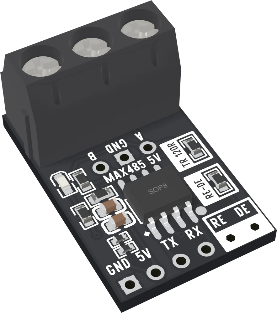
| Pins | GND, 5V or 3V3, TX (the chip's RO, to your RX), RX (the chip's DI, from your TX), RE and DE, on a 2.54 mm row. A, GND and B on a 5.0 mm screw terminal and again on three 2.54 mm holes |
| Termination | 120 Ω between A and B, fitted on every board. Keep it on the two boards at the ends of the cable and remove it from every board between them |
| Bias | 20 kΩ from A to the supply and 20 kΩ from B to GND on every board, and 10 kΩ pull-ups on TX and RX |
| Direction | RE joined to DE by a 0 Ω link, so 1 pin sets the direction: HIGH to talk, LOW to listen. Desolder the link to drive them separately |
| Speed | Up to 2.5 Mbit/s (MAX485) and 10 Mbit/s (MAX3485), the datasheets' figures. Runs up to about 1200 m at slow rates; up to 32 standard receivers on one bus |
| Board | 15.76 × 24.42 mm, 1.6 mm thick; 11.50 mm tall at the terminal. Headers ship loose, straight and right-angle |
| Revision | None printed; the model files are released as v1.0 |
What it does
A UART wire is fine across a desk and unreliable across a room. These boards turn a UART's TX and RX into RS485: every bit sent as a difference between two wires, A and B, which noise cannot easily change. Up to 32 standard receivers share one twisted pair, and the pair can run for hundreds of metres.
Two boards
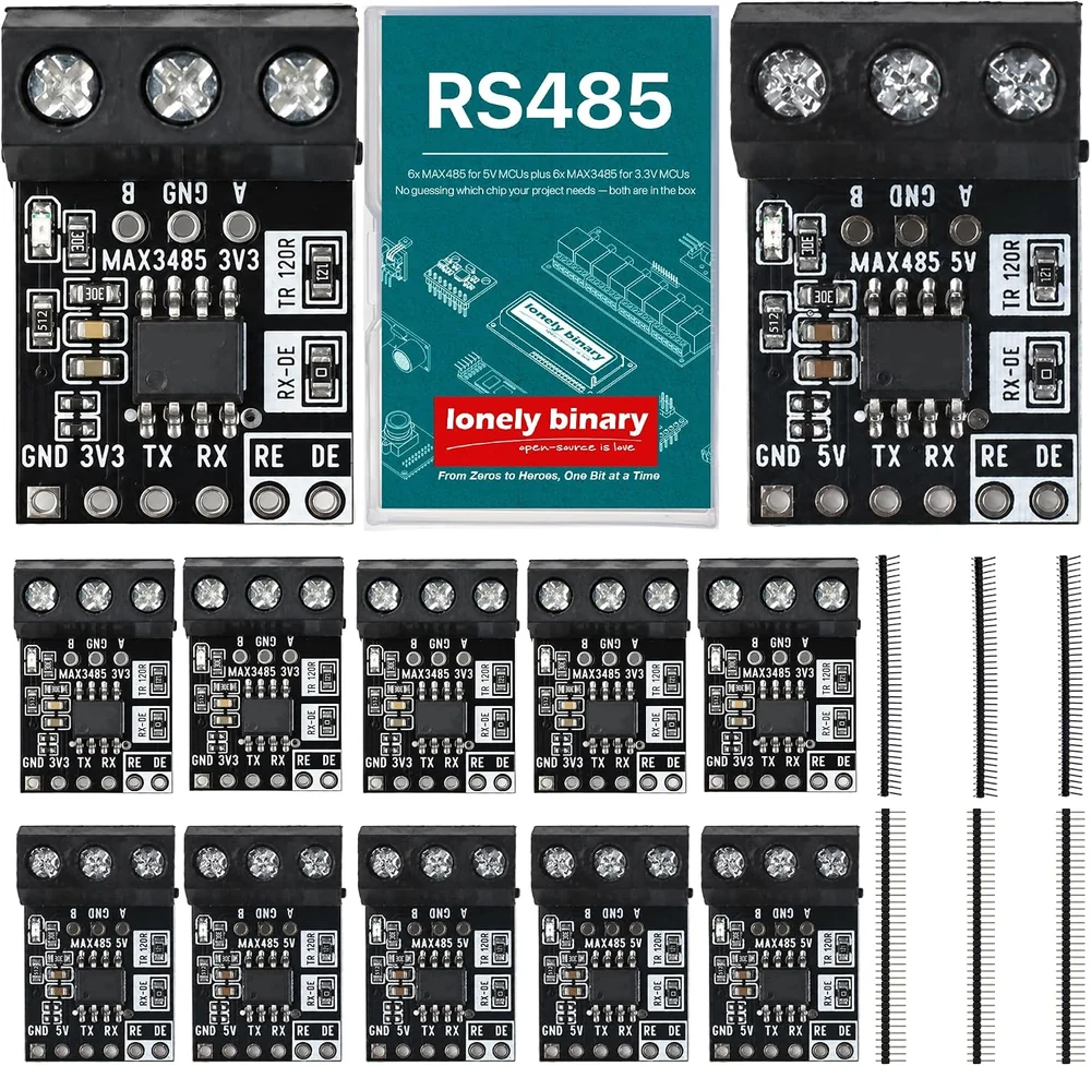
| MAX485 board | MAX3485 board | |
|---|---|---|
| Printed | MAX485 5V | MAX3485 3V3 |
| For | Arduino Uno, Nano, Mega | ESP32, Pico, STM32 |
| Supply | 4.75 to 5.25 V | 3.0 to 3.6 V |
| Fastest | 2.5 Mbit/s | 10 Mbit/s |
Six of each come in one 12-pack. They share a bus: pick each for the microcontroller it is wired to.
Two things to know before wiring
- The 120 Ω between A and B is fitted on every board. It belongs only on the two boards at the ends of the cable. Two boards: keep both. More: remove it from every board in between.
- RE and DE are joined by a 0 Ω link, so one GPIO sets the direction: HIGH
to talk, LOW to listen. Set it LOW first thing in
setup().
Wiring, in four lines
- GND to GND, and the board's 5V or 3V3 to the matching supply pin.
- The board's TX to your RX, and its RX to your TX.
- RE or DE (they are joined) to one GPIO.
- A to A, B to B and GND to GND between boards, on one twisted pair.
Where to start
The handbook below is eleven short articles. Read What is in the box to pick the board, Six pins and a terminal before wiring, and the three articles on the 120 Ω resistor before building a bus of more than two. One ESP32, two boards is the fastest way to prove a pair of boards works.
When it doesn’t work
- Which board do I use with an ESP32?
- The MAX3485 board, printed 3V3, powered from the ESP32's 3V3 pin. The MAX485 board's TX swings to 5 V and is pulled up to 5 V, which an ESP32 pin is not built to take.
- Which board do I use with an Arduino Uno?
- The MAX485 board, printed 5V, powered from the Uno's 5V pin. The MAX3485 board's TX is only guaranteed to reach 2.9 V for a 1, and the Uno is only guaranteed to read a 1 from 3.0 V.
- Do I need to remove the 120 Ω resistor?
- Only on boards in the middle of a bus. The resistor belongs at the two ends of the cable. With two boards, keep both. With the whole box on one cable, keep it on the first and last board and remove it from the ten between.
- Why are RE and DE joined?
- So one GPIO sets the direction, which is what nearly every RS485 library and example expects. HIGH switches the driver on and the receiver off; LOW does the reverse. Desolder the 0 Ω link in the box printed RE-DE to drive them from two pins.
- Do I need to connect GND between boards?
- Yes. The receivers need A and B within −7 to +12 V of their own ground, and boards on separate supplies share no ground unless a wire gives them one. The screw terminal's middle position is for that wire.
- Can a MAX485 board and a MAX3485 board share a bus?
- Yes. The bus carries only the difference between A and B, which both chips make and read the same way. Match each board to its own microcontroller.
- Does it do Modbus?
- It carries any bytes a UART sends, so Modbus RTU works over it with a Modbus library in the sketch. The board itself knows nothing about the protocol.