Six pins and a terminal
Six holes along the bottom go to your microcontroller, and three screws along the top go to the bus. The one name that trips everybody is TX: it is the board's own transmit, the chip's receiver output, and it goes to your RX.
Two sides
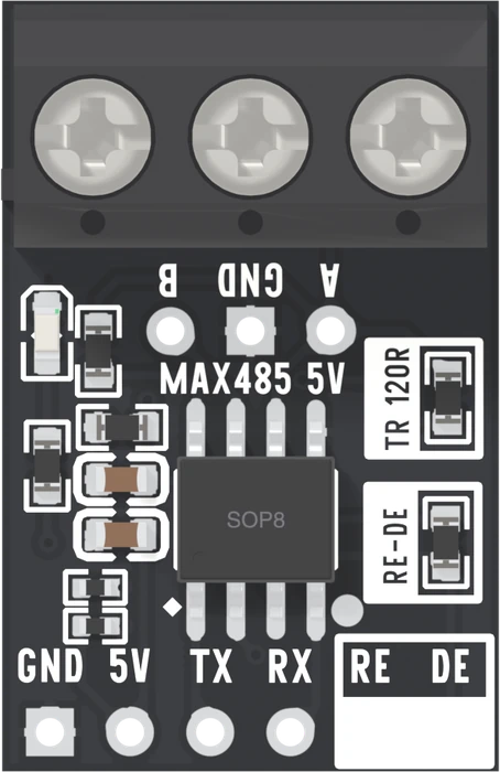
The board has two sides. Along the top, a screw terminal with B, GND and A, and three holes under it that carry the same three nets: this side goes to the other boards. Along the bottom, six holes for your microcontroller.
The six holes
| Hole | The chip calls it | Wire it to |
|---|---|---|
| GND | GND | GND |
| 5V or 3V3 | VCC | The matching supply pin |
| TX | RO, receiver output | Your RX |
| RX | DI, driver input | Your TX |
| RE | receiver enable | One GPIO, with DE |
| DE | driver enable | One GPIO, with RE |
TX and RX are named from the board's side, the way a USB-serial adapter names them. The chip's own names say it more plainly: RO is what it heard on the bus, coming out to you; DI is what you give it to put on the bus. Wire TX to TX and nothing moves in either direction, with no error anywhere.
What else is on the board
Every part is on both boards, with the same value:
- 120 Ω between A and B, in the box printed TR 120R. It belongs on the two boards at the ends of a cable and nowhere else, and it ships fitted on all twelve. The 120 Ω resistor is about it.
- A 0 Ω link between RE and DE, in the box printed RE-DE.
- 20 kΩ from A up to the supply and 20 kΩ from B down to GND, which hold the bus at a 1 while nobody is talking — as far as the 120 Ω lets them.
- 10 kΩ pull-ups on TX and RX, so neither line floats while your microcontroller is starting up.
- 100 nF and 10 µF across the supply, and a power LED.
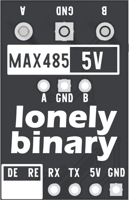
From underneath, everything reads mirror-image: the bottom row starts with DE on the left. When you wire from the back, go by the printing on the back.
When it does not work
The board names its pins from its own side. Its TX is what it sends to you, so it goes to your RX; its RX takes your TX. Swap the two wires. Nothing is damaged by having them crossed the wrong way.
Either. The 0 Ω link on the board joins them, so they are one net and one wire to either hole drives both. Wiring both holes to the same GPIO is also fine.
They are the same three nets, A, GND and B, so either. The screw terminal takes stripped cable for a real run; the three holes take a header or jumper wires on a bench.
The LED sits across the supply through a 5.1 kΩ resistor, so if it is dark the board has no power: check the 5V or 3V3 hole and GND. It is dim by design, especially on the 3.3 V board.
One pin decides whether the board talks or listens, and why that is the default.
RE and DE are joined →Edit this page — content/books/rs485/six-pins-and-a-terminal.mdx
Questions about this product
See what other owners have asked, and read their solutions.
This page covers several products. Choose yours to see the right discussions.
Discuss this article
Ask about this page. The answer stays here, on the page it belongs to, for whoever hits the same wall next.