Only the two ends keep it
Every board ships with its 120 Ω fitted, so twelve boards straight from the box put twelve terminators across one pair: 10 Ω, where the chips are specified for 54. Keep the resistor on the two boards at the ends of the cable and take it off every board between them.
Twelve in parallel
Every terminator sits straight across A and B, so every one you leave fitted is another path for the driver's current, in parallel with the rest. Twelve 120 Ω resistors in parallel are 10 Ω.
Both datasheets guarantee the driver's swing — at least 1.5 V between A and B — into 54 Ω, which is two terminators with a full bus of receivers on them. With two fitted, the driver sees 60 Ω and needs about 25 mA. With twelve, it would need 150 mA for the same swing, well past what the chip is specified to give. It makes a smaller swing instead, and gets warm doing it.
On a desk that smaller swing is still plenty. On a long cable it is the margin noise eats first.
Which boards keep it
The two at the ends of the cable — the first and last boards along it, not the first and last you happened to wire. Which board talks most does not matter; where it sits on the cable does.
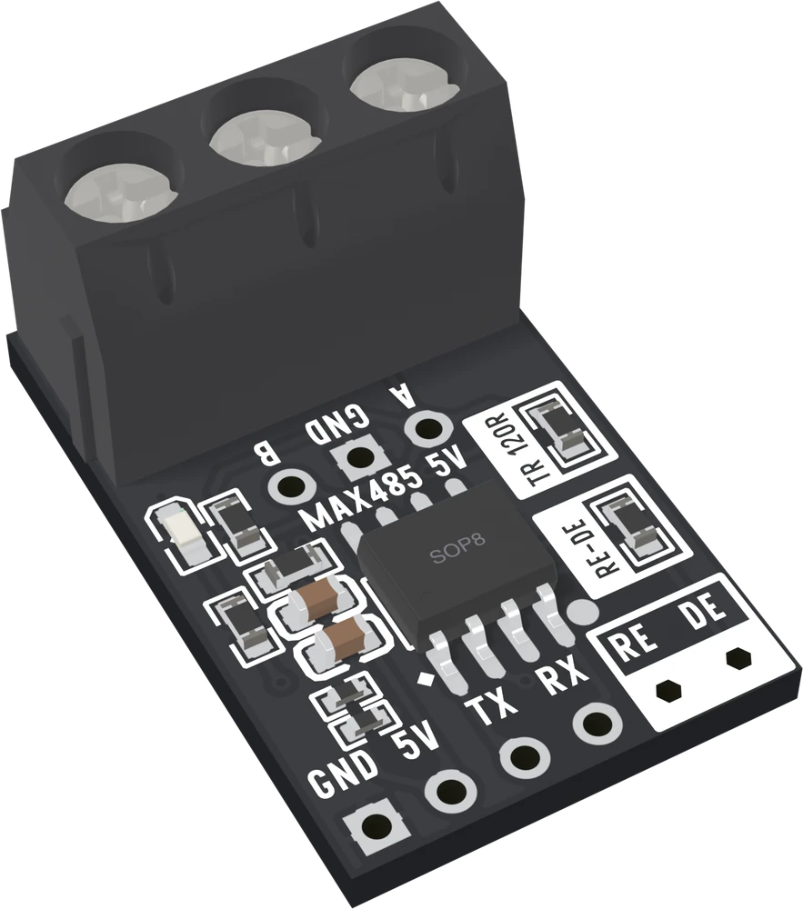
Taking it off
The terminator is a small surface-mount resistor, 1.6 × 0.8 mm. With a soldering iron:
- Add a little fresh solder to the tip, and hold it against one end of the resistor until that end's solder melts.
- Push the resistor sideways off that pad with tweezers or the tip itself, then melt the other end and lift it away.
- Check with a meter: across A and B on the terminal should now read thousands of ohms, not 120.
Work on the boards before you wire them up, and keep the resistors. If a board later becomes an end, a through-hole 120 Ω in the screw terminal between A and B does the same job without soldering anything.
A quicker rule for small buses
With three boards on a short cable, removing the middle one's resistor is enough. With the whole box on one long run, take ten off and keep two. When in doubt, measure across A and B with the power off: about 60 Ω is right for any bus, 120 means one end is missing its resistor, and anything under about 50 means too many are still fitted.
When it does not work
No. Two boards are the two ends of their cable, so both keep their 120 Ω. That is the bus the chips are designed for, and it is what the builds in this book use.
You do not have to solder it back. Put an ordinary 120 Ω through-hole resistor into the screw terminal, one leg under A and one under B, and tighten both screws. Electrically that is the same resistor in the same place.
On a short cable it often does work: the driver makes a smaller swing, and a short cable does not need much. The margin is what goes. On a long run with noise on it, a bus that was working starts dropping bytes, and nothing on the bench explains why.
Better not. A blade that slips cuts a track or the chip's pins, and a half-cut resistor can still conduct. Heat and lift it, and if you have no iron, leave it and plan the bus so that board sits at an end.
What the bus reads between messages, and why the 120 Ω decides it.
When nobody talks →Edit this page — content/books/rs485/only-the-two-ends.mdx
Questions about this product
See what other owners have asked, and read their solutions.
This page covers several products. Choose yours to see the right discussions.
Discuss this article
Ask about this page. The answer stays here, on the page it belongs to, for whoever hits the same wall next.