The two boards
One board takes the card out of your phone, the other takes the card out of your camera. Electrically they are the same circuit twice, and the only difference that matters is two extra holes marked CD and WP.
Same circuit, twice
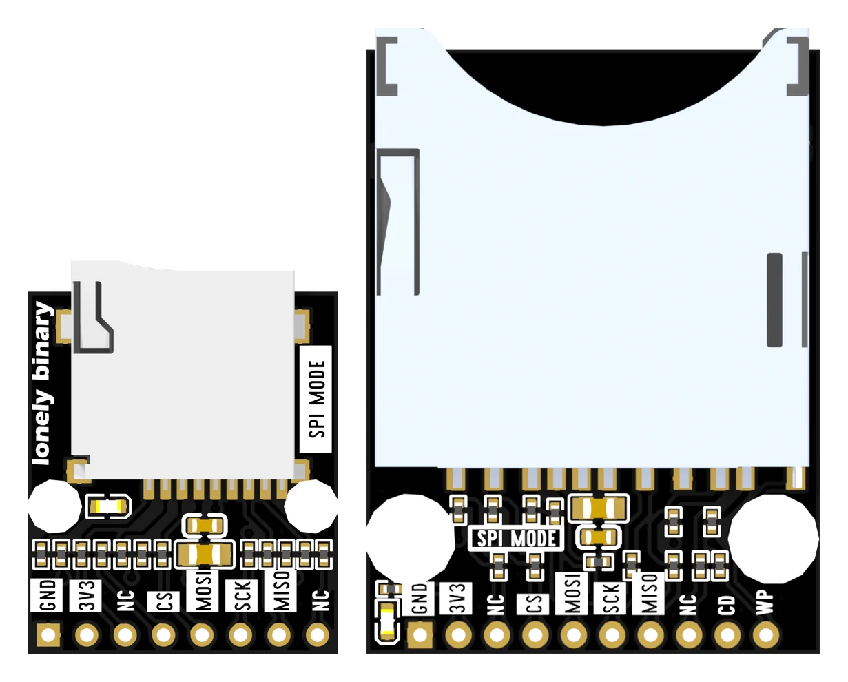
Both boards put six signals in series with a 22 Ω resistor, pull the lines the card wants held high up to 3V3 through 10 kΩ, decouple the supply with a 10 µF and a 100 nF in parallel, and light an LED. The full-size socket brings out two mechanical switches as well, which is why it has seven pull-ups where the microSD board has five, and ten holes where the microSD board has eight.
The two extra holes
CD is card detect: a metal finger inside the socket that a card pushes onto ground. WP is write protect: a switch under the little plastic slider on the side of a full-size card. Neither is part of the SD bus. Neither does anything unless your sketch reads it.
A microSD card has no lock tab at all, and this microSD socket brings out no detect contact, so there is nothing for the smaller board to bring out. Card detect and write protect is the whole of what those two holes are for.
Choosing between them
The card you already own decides it. If your spare cards came out of a phone or a drone, the microSD board is the one — and it is under half the area, which on a breadboard is the difference between fitting beside an ESP32 and not. If your spare cards came out of a camera, the full-size board saves you an adapter and gives you the two switches for free.
Both are sold together as one set for the same reason this book covers both: everything past the socket is identical.
When it does not work
No. On the bench the two were within a hundredth of a megabyte per second of each other in SPI and in 1-bit mode. The microSD board was actually the faster of the two in 4-bit mode, and that was the wiring on the day rather than the board — see Four wires, one clock.
Yes, in the plastic adapter that came with it. The adapter is wires and nothing else, so the card behaves the same. The lock tab on the adapter works too, which means a forgotten tab on an adapter is a real way to confuse yourself.
Almost never. They are mechanical switches, not part of the card bus, and a sketch that ignores both works perfectly. They earn their place in something that runs unattended, where printing 'no card' is better than printing a mount failure.
Both headers are 2.54 mm, so they do fit — but a single row sits along one edge of the board, which means the board overhangs rather than straddling the centre channel. Put it at the end of the breadboard with the header in one row of holes.
The two holes marked NC, and what is printed beside them on the other face of the same board.
Both sides of the header →Edit this page — content/books/sd/the-two-boards.mdx
Questions about this product
See what other owners have asked, and read their solutions.
This page covers several products. Choose yours to see the right discussions.
Discuss this article
Ask about this page. The answer stays here, on the page it belongs to, for whoever hits the same wall next.