Three volts three, and nothing else
The bill of materials for both boards is a socket, eleven resistors, two capacitors and an LED. There is no regulator and no level shifter, which means whatever your board puts on the header lands on the card unchanged.
The whole bill of materials
Both boards are the same short list. On the microSD board: one socket, six 22 Ω resistors, five 10 kΩ resistors, one 5.1 kΩ resistor, a 10 µF and a 100 nF capacitor, and a red LED. The full-size board is the same with two more 10 kΩ resistors, for the two switches its socket has.
That is the list. There is no regulator on it and no level shifter on it, and those two absences are the only thing on this page.
An SD card is a 3.3 V part. Its supply range is 2.7 V to 3.6 V, and a signal above its supply is out of spec on any input. With nothing in the wires, your board's logic level is the card's logic level.
Why the board is built this way
Because the parts that would protect you also get in the way. A regulator drops a volt and needs current it cannot always supply on a burst; a buffer adds propagation delay and a direction problem, because the data lines go both ways. Leaving both out is what lets this board run 4-bit mode at 40 MHz — which the buffered modules cannot do, because their buffers only pass signals one way and only cover the four wires SPI uses.
It is a board for a 3.3 V host, and on a 3.3 V host it is the simplest thing that can work.
The LED
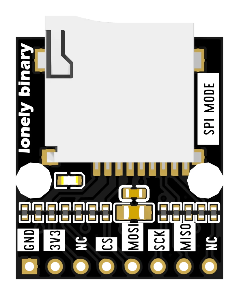
The LED is on whenever the board has 3.3 V. It is not connected to a GPIO, it does not blink on card activity, and it cannot be turned off. If it is dark, check the 3V3 wire before you check anything else.
When it does not work
That is a different board. The common blue microSD adapter carries an AMS1117 regulator and a 74-series buffer, so it takes 5 V on its VCC pin and shifts the signals down. These two boards carry neither part — check the pictures: there is no eight-pin chip and no three-pin regulator anywhere on them.
No. That hole is the card's supply, wired straight to the socket through nothing but a pair of decoupling capacitors. 5 V on it is 5 V on the card. Find the 3V3 pin on your development board instead — every ESP32, Pico and Raspberry Pi has one.
That is the usual way this fails. A 3.3 V part driven at 5 V often works, sometimes for a long time, and then does not. Nothing about it working is evidence that it is within spec. If you need a card on a 5 V board, put a level converter in the four or six signal wires and feed the module from a real 3.3 V supply.
On an ESP32 development board it is usually printed 3V3 or 3.3V and sits near the USB end. Do not use VIN or 5V. If your board has only 5 V out, it cannot drive this module directly.
One circuit, two sockets, and the two extra holes that are the only electrical difference between them.
The two boards →Edit this page — content/books/sd/three-volts-only.mdx
Questions about this product
See what other owners have asked, and read their solutions.
This page covers several products. Choose yours to see the right discussions.
Discuss this article
Ask about this page. The answer stays here, on the page it belongs to, for whoever hits the same wall next.