Why the resistors are there
Every signal on these boards passes through 22 Ω, and every signal except one is pulled up to 3V3 through 10 kΩ. The exception is the clock, and why it is the exception explains what both sets of resistors are for.
One line, three components
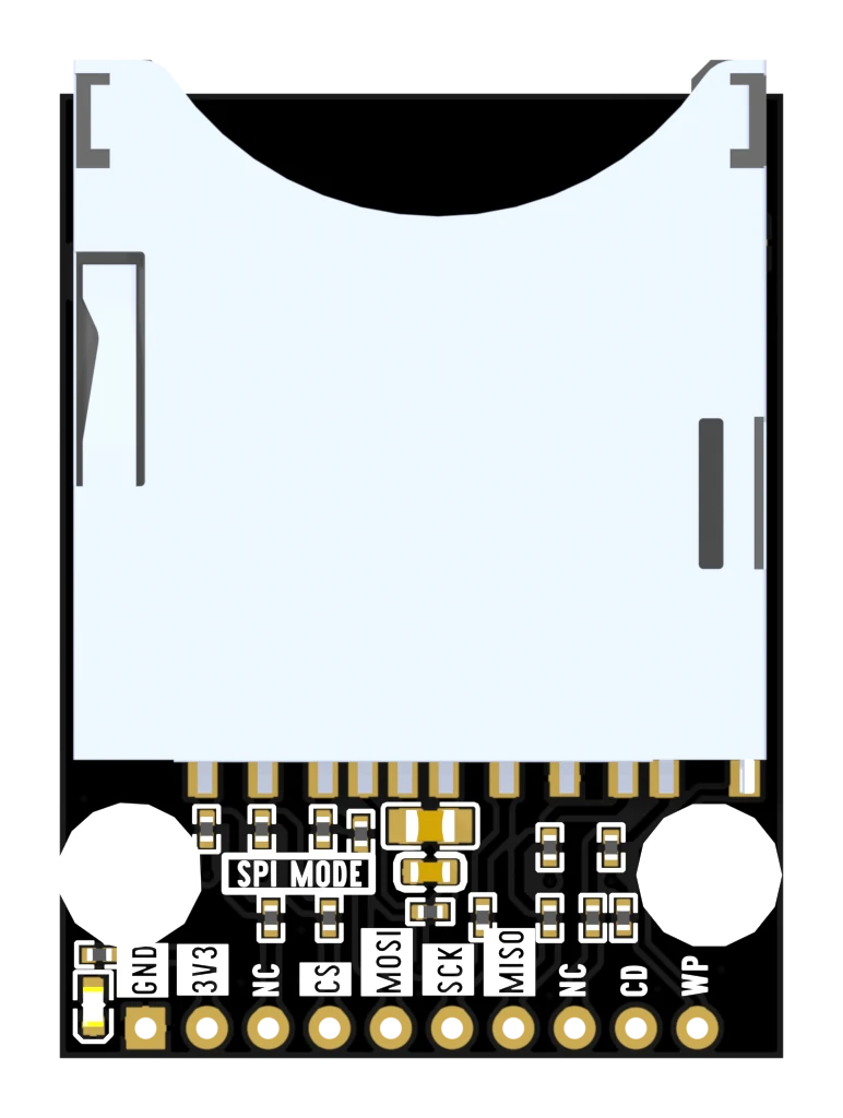
Every bus line on both boards is the same three things: a hole, a 22 Ω resistor in series with it, and — on all but one line — a 10 kΩ resistor up to 3V3. The pull-up sits between the series resistor and the card, which is deliberate: the SD bus wants its pull-ups as close to the card as they can be.
The 22 Ω
A fast edge on a wire behaves like a wave, and when it reaches the far end it partly bounces back. On a short trace nobody notices. On six dupont wires and a breadboard at 40 MHz, the reflection lands on top of the next edge and the card reads a bit that was never sent.
22 Ω in series takes the energy out of the edge without slowing the line down enough to matter. It is the cheapest fix for a problem you would otherwise diagnose as "the card is unreliable".
The 10 kΩ
The command line and the data lines are shared: the host talks on them, and then lets go so the card can answer. In the gap, nobody is driving. A floating input reads whatever the air near it is doing.
So every line that changes hands gets a resistor holding it high while neither end is talking. On the full-size board, CD and WP get one too — not because they change hands, but because an open switch is exactly the same problem.
The clock is the exception
The host drives the clock from the first edge to the last and never lets go of it. There is no gap to fill, so a pull-up would do nothing except add a little capacitance to the one line that can least afford it.
That is why the clock is the only bus line on either board with no resistor to 3V3 — and it is a good check on any SD wiring you meet. If the clock has a pull-up, somebody was copying rather than thinking.
And the LED
When it does not work
No. The board fits them: five on the microSD version and seven on the full-size one, all 10 kΩ to 3V3, and they sit on the socket side of the series resistors where the SD bus wants them. Adding more in parallel only makes the lines harder to pull low.
Not measurably at these speeds. It works against the capacitance of the wire, and 22 Ω against the few tens of picofarads a jumper wire brings is well under a nanosecond — against a clock period of 25 nanoseconds at 40 MHz. What it buys is a softer edge, which is what stops that edge ringing on a long wire.
Because nothing is signalling on them. They are mechanical contacts that either touch ground or do not, so there is no edge to soften. They do get the 10 kΩ pull-up, which is what makes an open switch read HIGH instead of floating.
It already has two — a 10 µF and a 100 nF across 3V3 and GND, next to the socket. A card draws current in bursts while it writes, and those two are what keeps the supply from sagging during one. There is nothing to add.
What three modes actually measured on one card, sustained and sprinting, and the gap between those two numbers.
How fast it goes →Edit this page — content/books/sd/why-the-resistors-are-there.mdx
Questions about this product
See what other owners have asked, and read their solutions.
This page covers several products. Choose yours to see the right discussions.
Discuss this article
Ask about this page. The answer stays here, on the page it belongs to, for whoever hits the same wall next.