Specifications
| Boards | 2 readers, sold separately or as a set: one microSD, one full-size SD. The same circuit either side of the socket |
|---|---|
| Supply | 3.3 V only, on the 3V3 hole. There is no regulator and no level shifter on either board, so a 5 V host needs a converter in the signal wires and a real 3.3 V supply here |
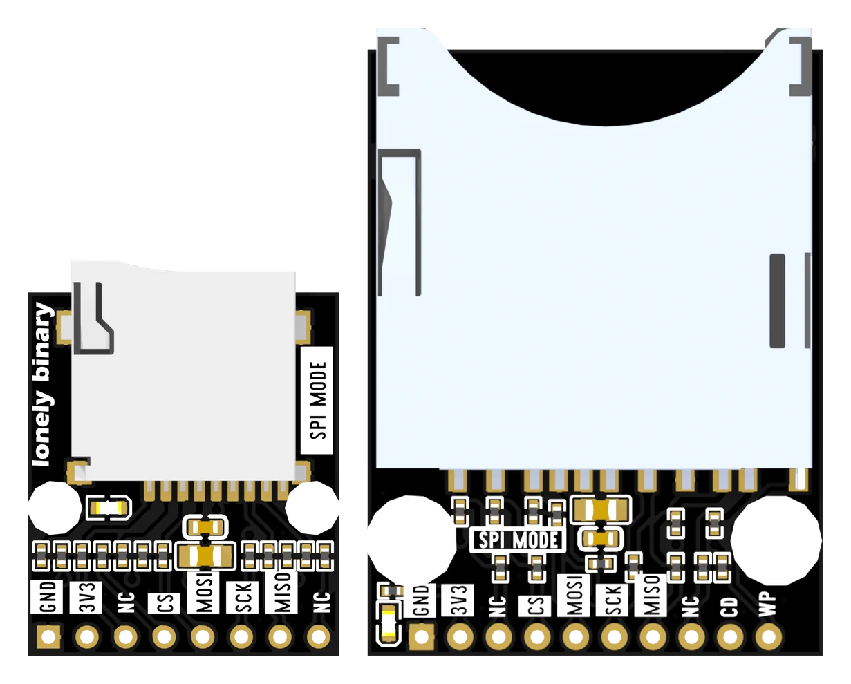
| Header, microSD | 8 holes on 2.54 mm pitch. Front: GND, 3V3, NC, CS, MOSI, SCK, MISO, NC. Back, for the same holes: GND, 3V3, DATA2, DATA3, CMD, CLK, DATA0, DATA1 |
| Header, full-size SD | 10 holes on 2.54 mm pitch: the same eight in the same order, then CD and WP |
| Bus modes | SPI, SD_MMC 1-bit and SD_MMC 4-bit. Measured sustained read 1.56, 2.67 and 3.80 MB/s, and a sprint peak of 5.04 MB/s in 4-bit mode |
| Signal resistors | 22 Ω in series with CMD, CLK and DATA0 to DATA3 on both boards. 10 kΩ to 3V3 on every bus line except the clock: five on the microSD board, seven on the full-size one |
| Card detect and write protect | 2 mechanical switches in the socket, CD and WP, each pulled up to 3V3 through 10 kΩ. Full-size board only, and neither is part of the card bus |
| Sockets | microSD: push-push TF PUSH, specified for 5000 insertions at 0.3 A per contact. Full size: push-push SD-106M with the two switches |
| Decoupling | 10 µF and 100 nF across 3V3 and GND beside the socket, for the current a card draws in bursts while it writes |
| Power LED | Red, from 3V3 through 5.1 kΩ to ground — roughly 0.3 mA. On whenever the board has power, and on no GPIO |
| Size | microSD 20.5 × 26.1 mm, full-size SD 30.0 × 41.4 mm, two mounting holes each |
| Card formats | FAT32 and exFAT, which is what the ESP32 core's SD and SD_MMC libraries mount |
What it does
Both boards are a card socket with the SD bus brought out to a 2.54 mm header, and almost nothing else: six 22 Ω resistors in series with the signals, a bank of 10 kΩ pull-ups, a decoupling pair, and a power LED.
There is no regulator and no level shifter. That is what lets them run the card at its own speed — and it is why they are for 3.3 V hosts only.
The two NC pins
The front of each board is printed with SPI names and two holes marked NC. The back of the same board is printed with the SD bus names for the same holes, and there those two read DATA2 and DATA1.
Both faces are correct. NC means not needed in SPI mode, which is the mode the
front is labelled for. Wire those two holes as well, switch to SD_MMC.h, and
the card runs four data lines instead of one.
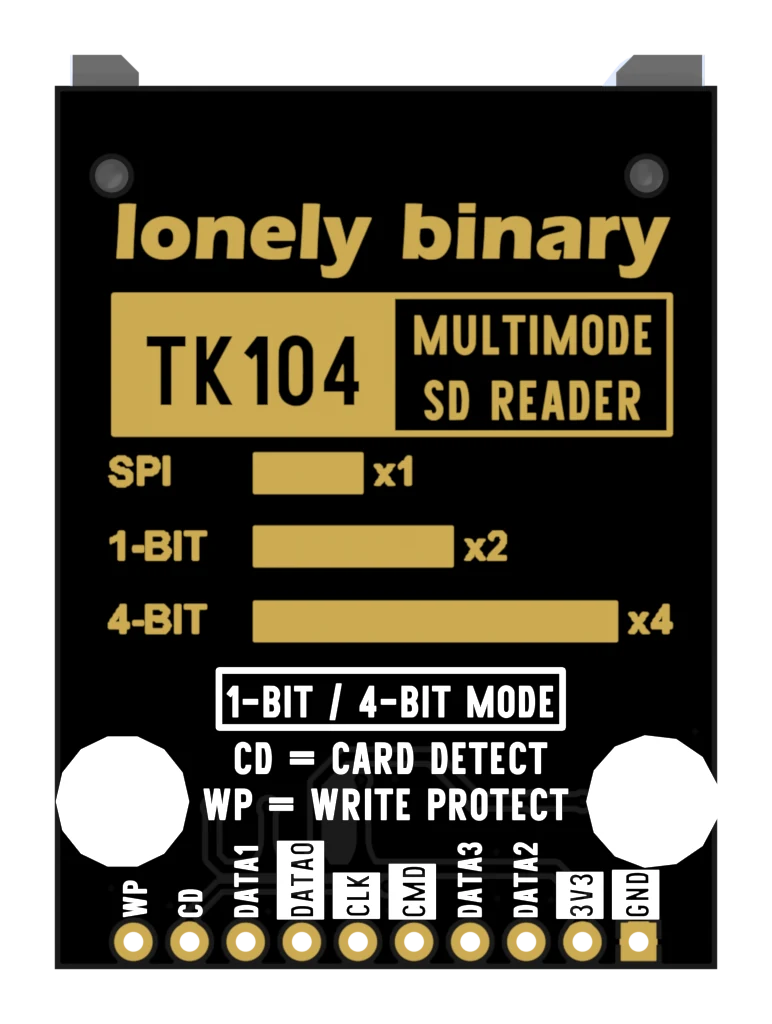
| Front | Back | SPI | 1-bit | 4-bit |
|---|---|---|---|---|
| GND | GND | GND | GND | GND |
| 3V3 | 3V3 | 3.3 V | 3.3 V | 3.3 V |
| NC | DATA2 | — | — | D2 |
| CS | DATA3 | CS | — | D3 |
| MOSI | CMD | MOSI | CMD | CMD |
| SCK | CLK | SCK | CLK | CLK |
| MISO | DATA0 | MISO | D0 | D0 |
| NC | DATA1 | — | — | D1 |
| CD | CD | switch | switch | switch |
| WP | WP | switch | switch | switch |
The last two rows are on the full-size board only, and no bus mode uses them.
Which board
| microSD | Full-size SD | |
|---|---|---|
| Takes | the card from a phone or drone | the card from a camera |
| Holes | 8 | 10 |
| Card detect, write protect | no | yes |
| Size | 20.5 × 26.1 mm | 30.0 × 41.4 mm |
| Speed | the same | the same |
The card you already own decides it. The set has one of each.
Wiring, in four lines
- 3V3 to your board's 3.3 V pin — not 5 V, and not VIN.
- GND to ground, with as short a wire as the signals get.
- Then four signals for SPI: CS, MOSI, SCK, MISO, on any four free GPIOs.
- Or six for 4-bit mode: those four plus the two holes printed NC, and
SD_MMC.hinstead ofSD.h.
Where to start
The handbook below is eleven short articles with a working figure in each. If you only read one, read both sides of the header. If you want a file on a card in the next ten minutes, your first file is the sketch and the six wires, written out.
When it doesn’t work
- Are the pins marked NC really not connected?
- No — and this is the one thing to know about these boards. Both are wired to the card through a 22 Ω resistor and pulled up to 3V3 through 10 kΩ, exactly like the four SPI signals. Turn the board over and the same two holes are printed DATA2 and DATA1. NC means not needed in SPI mode, which is what the front of the board is labelled for. Wire those two as well and you get 4-bit mode, which measured about two and a half times the read speed.
- Can I use this with a 5 V Arduino?
- Not directly. An SD card is a 3.3 V part with a supply range of 2.7 to 3.6 V, and there is no regulator and no level shifter anywhere on either board — whatever your host puts on the header lands on the card. A 5 V board needs a level converter in the four or six signal wires and a separate 3.3 V supply on the 3V3 hole. If you have the choice, use a 3.3 V board instead.
- Which is faster, the microSD board or the full-size one?
- Neither. They are the same circuit, and on the bench they matched to within a hundredth of a megabyte per second in SPI and in 1-bit mode. In 4-bit mode the microSD board settled at 40 MHz and the full-size board at 26 MHz on the same card on the same day, and the difference was six jumper wires of unequal length rather than the boards.
- It mounted once and now SD_MMC.begin() fails.
- A card that has answered in SPI stays in SPI until its supply is removed, so running an SD.h sketch and then an SD_MMC.h one on the same power-up will not work. Unplug the board — the reset button restarts the microcontroller and leaves the card powered.
- Do I need CD and WP?
- Almost never. They are mechanical switches, not bus lines, and a sketch that ignores both works perfectly. Note also that nothing enforces the write-protect tab: a locked card mounts and takes writes unless your own sketch reads WP and refuses.
- Which card should I buy?
- A small, ordinary one from a brand you recognise — 4 to 32 GB, class 10, formatted FAT32 or exFAT. A faster card buys nothing here: the quickest thing measured on these boards was 5.04 MB/s, which the slowest card on a shop shelf will beat. What a fake card will do is lose your data at the point its real capacity runs out.