Four plugs, in order
Two cables to the printer, one header to your board, and the charger last. The order is not fussiness — the last plug is the one that makes everything live.
What is in the box
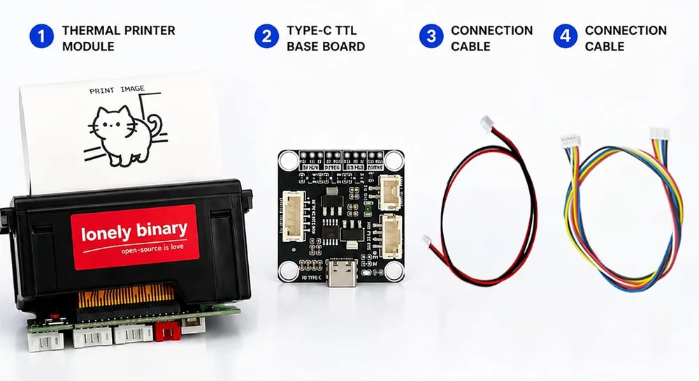
Four items, and two of them are cables that each go in exactly one place: the red-and-black one carries 9 V to the printer, the coloured one carries serial.
The order
Printer power and printer data first, your microcontroller next, the USB-C charger last. Everything before the charger is dead metal; after it, the 9 V rail is live and your board is running.
That is the whole argument for the order. Fitting a five-pin header onto a powered board, one row away from a row at a different voltage, is a slip away from damage. Fitting it to an unpowered board is not.
Which pins, concretely
For an ESP32-S3 on the 3V3 MCU header, with the sketches in this book:
| Base board | Your board |
|---|---|
TX | GPIO16 (the port's RX) |
RX | GPIO17 (the port's TX) |
3V3 | 3V3 |
GND | GND |
For an Arduino Uno on the 5V MCU header, the same four with TX to D10 and
RX to D11, and 5V to 5V.
The ESP32-S3's serial pins are a choice rather than a fact — the chip can route a UART almost anywhere. These sketches use GPIO16 and GPIO17 on UART2 because UART0 is already carrying the Serial Monitor over the USB cable, and borrowing those pins means losing the one tool that tells you what your sketch is doing.
Before the charger goes in
Check three things, because all three are silent when wrong: the printer's power
cable is in the printer's power socket and not its data socket, your board is on
the header matching its voltage, and TX is opposite your board's RX.
When it does not work
Each plug fits its own socket one way round, which is the good news. The hazard is the socket, not the orientation: the printer power cable fits the printer power socket and the MCU header takes a different connector entirely, but the two MCU rows accept the same header and sit next to each other.
Swap TX and RX at the base board end. The labels are from the board's point of view, so the board's TX goes to your board's RX. Getting this wrong is invisible — no smoke, no error, just silence — and it is the second most common cause after the supply.
Only to read status back. Printing needs one direction: your board's TX to the printer's RX, plus a common ground. Asking the printer whether it has paper needs the return wire too, which is why the status article assumes it.
The head pulling its peak current is dragging the supply down far enough to reset the microcontroller sharing it. A shorter or thicker USB-C cable usually fixes it; powering the board from its own USB cable, with only TX, RX and GND shared, always does.
One number decides whether words or rubbish come out, and the two printers do not share it.
The baud rate is printed on the unit →Edit this page — content/books/thermal-printer/four-plugs-in-order.mdx
Questions about this product
See what other owners have asked, and read their solutions.
This page covers several products. Choose yours to see the right discussions.
Discuss this article
Ask about this page. The answer stays here, on the page it belongs to, for whoever hits the same wall next.