One board, two rails
The base board turns one USB-C cable into a 9 V rail for the printer and a logic supply for your microcontroller. There are two headers for that second job, five pins each, and they are not interchangeable.
One cable in, three things out
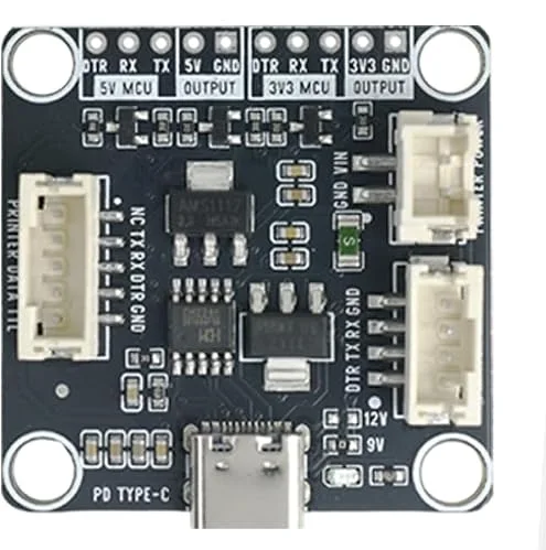
The USB-C socket at the bottom is the only input. Out of it come three things: 9 V on the printer power socket, serial on the printer data socket, and a supply plus serial for your own board on one of the two headers along the top.
The 9 V rail is not one of your options. It leaves the board on its own socket, goes to the printer, and should never be anywhere near a microcontroller pin.
The two rows that look the same
Along the top edge are two five-pin rows printed with the same five names in
the same order — DTR RX TX and then a supply pin and a ground. The only
difference is the supply: one row is 5V MCU and the other is 3V3 MCU.
That similarity is the hazard. The rows are adjacent, the pin order is identical, and a header pushed onto the wrong one fits perfectly. What changes is what your board's RX pin is connected to — and a 5 V transmitter driving a 3.3 V input is the mistake that costs a development board rather than an evening.
- 3V3 MCU — ESP32, ESP32-S3, Raspberry Pi Pico, anything that runs at 3.3 V.
- 5V MCU — Arduino Uno, Nano, Mega, anything that runs at 5 V.
RX and TX cross over
The board's TX goes to your board's RX, and its RX to your board's TX. The
labels on the header are from the base board's point of view, so wiring TX to
TX produces two transmitters shouting at each other and a printer that never
hears anything.
DTR is a flow-control line the printers can use to say "stop sending, my
buffer is full". None of the sketches in this book use it, and leaving it
unconnected is fine at these speeds and these message sizes.
When it does not work
The one marked 3V3 MCU. Every ESP32, every ESP32-S3 and a Raspberry Pi Pico are 3.3 V parts, and the 5V MCU row above would put 5 V on pins built for 3.3 V. An Arduino Uno is the other way round and belongs on 5V MCU.
Unplug the charger before anything else. A 3.3 V board fed 5 V on its supply pin may be fine — many carry a regulator on that pin — but 5 V arriving on a bare GPIO through the RX line is the one that does damage. Check the board still enumerates over USB before you use it in anything that matters.
Yes, and it is a reasonable way to work while you are uploading sketches. Leave the MCU header's supply pin unconnected and wire only TX, RX and GND, so the two boards share a ground without fighting over who supplies the 3.3 V.
It is the regulator that makes the 3.3 V rail on the 3V3 MCU header. It drops from the board's internal supply, so that rail is good for a microcontroller and not for anything that draws real current, such as a motor or a second display.
The two boxes share this board and almost nothing else. What actually differs, and which one you have.
Receipts and labels are different machines →Edit this page — content/books/thermal-printer/one-board-two-rails.mdx
Questions about this product
See what other owners have asked, and read their solutions.
This page covers several products. Choose yours to see the right discussions.
Discuss this article
Ask about this page. The answer stays here, on the page it belongs to, for whoever hits the same wall next.