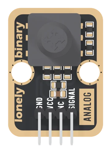
Specifications
| Type | A five-way navigation switch, up, down, left, right and a centre press, read on one analog pin through a resistor ladder |
|---|---|
| Switch | XUNPU WS-1001-ACW09026 under a black silicone cap: 250 ± 50 gf, 0.2 mm travel, 50,000 cycles, 50 mA and 12 V DC per contact at most |
| Output | One analog line, SIGNAL. It rests at 0 V; each push lifts it to its own fraction of VCC. Read it with analogRead |
| Levels | Up 1/9 of VCC, press 2/11, left 3/11, down 4/9, right all of VCC: 0.37, 0.60, 0.90, 1.47 and 3.30 V at 3.3 V |
| Supply | Your board's logic voltage on VCC: 5V on an Uno, 3V3 on an ESP32, ESP32-S3 or Pico. A push to the right puts VCC on the SIGNAL pin |
| Current | 0.066 mA at 3.3 V through the resistor chain, always; at most 0.4 mA while right is held |
| Pins to wire | 3 of 4: GND, VCC and SIGNAL. NC is connected to nothing on the board |
| Header | 4-pin right-angle male, 2.54 mm pitch: GND, VCC, NC, SIGNAL, with GND on the square pad |
| Board | 22.4 × 30.4 mm, two 4.8 mm mounting holes 16 mm apart. The back prints TK94 FIVE-DIRECTION JOYSTICK and UP, DOWN, LEFT, RIGHT, CENTER PUSH CONTROL |
| Height | 12.8 mm from the bottom of the board to the top of the cap (the mechanical drawing) |
| In the box | 1 × TK94 block with its cap and header fitted. It also ships inside the TinkerBlock kits |
What it does
A five-way navigation switch: tilt the cap up, down, left or right, or press it straight down. Each push joins SIGNAL to its own point of a chain of five 10 kΩ resistors between VCC and GND, and a sixth 10 kΩ holds SIGNAL at 0 V the rest of the time. So every push is a different voltage, and one analog pin tells all five apart.
With VCC at 3.3 V, and the block held with its header on the left:
| Push | SIGNAL | Of VCC |
|---|---|---|
| Nothing | 0 V | 0 |
| Up | 0.37 V | 1/9 |
| Press | 0.60 V | 2/11 |
| Left | 0.90 V | 3/11 |
| Down | 1.47 V | 4/9 |
| Right | 3.30 V | all |
The page this replaces described a different board: "five separate momentary switches" read with digitalRead on five digital lines, with pull-ups, and a reading that rests near 512. There is one line, no pull-up, and it rests at 0.
Two things to know before wiring
- VCC is your board's logic voltage. A push to the right puts VCC on SIGNAL: 5V on an Uno, 3V3 on an ESP32, ESP32-S3 or Pico.
- SIGNAL is analog. It goes to an ADC pin and is read with analogRead. A digital input calls right HIGH and the other four LOW.
Wiring, in four lines
- GND to your board's GND.
- VCC to 5V on an Uno; 3V3 on an ESP32, ESP32-S3 or Pico.
- NC to nothing.
- SIGNAL to an analog pin: A0 on an Uno, GPIO 34 on an ESP32, GPIO 4 on an ESP32-S3, GP26 on a Pico.
No library is needed.
Where to start
The handbook below is ten short articles, each with a working figure. The first read is the whole build. One step per push is a menu that counts each push once.
For how it works, read a ladder of resistors and telling them apart. If a reading looks wrong, when a reading is wrong.
When it doesn’t work
- Is it five separate switches on five pins?
- No. There is one output, SIGNAL. Each of the five pushes joins it to a different point of a chain of 10 kΩ resistors, so each is a different voltage on one analog pin. The page this replaced said five digital lines; that was wrong.
- Why does it read 0 with nothing pressed, not the middle?
- A 10 kΩ resistor holds SIGNAL at GND while no contact is closed. It is not a thumb stick that rests in the middle: the resting reading is 0, and each push jumps to its own level.
- Should VCC go to 3V3 or 5V?
- To your board's logic voltage: 5V on an Uno, 3V3 on an ESP32, ESP32-S3 or Pico. A push to the right joins SIGNAL straight to VCC, so 5V would put 5 V on a 3.3 V pin, and the sketch's lines assume VCC is what the ADC measures against.
- Which way is up?
- Hold the block with the header on the left, so the words on its front read across. That way up is a ninth of VCC and right is all of it, which is also how the maker's own sketch named them.
- What does NC do?
- Nothing. It is connected to nothing on the board; it is there so every four-pin TinkerBlock has the same header. Leave it empty.
- Letting go sometimes counts as another push.
- SIGNAL takes about 3 ms to fall to 0 after a release, through every lower level, because a 100 nF capacitor drains through 10 kΩ. Believe a reading only after it has held for about 10 ms, as the menu sketch does.
- Can it tell a diagonal?
- No. Two contacts at once read as somewhere between their levels, usually as the higher push. Up and left together read as a press.