Specifications
| Type | Slotted optical interrupter |
|---|---|
| Output | Digital, changes when the slot is blocked |
| Slot width | About 5 mm |
| Supply voltage | 3.3 V or 5 V |
What it is
An infrared emitter on one side of a gap and a detector on the other. Something in the gap breaks the beam.
Attach a disc with slots cut in it to a shaft, put the disc through the gap, and each slot passing gives a pulse. Count pulses per second and you have speed; count them over time and you have distance travelled.
Because it is optical there is nothing to wear out and no bounce, which is why it handles speeds a reed switch could not. The limit is the interrupt rate: at high RPM with a many-slotted disc you can generate pulses faster than the loop can count, so put it on a hardware interrupt and keep the handler to a single increment.
It also works as a simple presence detector — an end-stop, or a "the drawer is closed" switch.
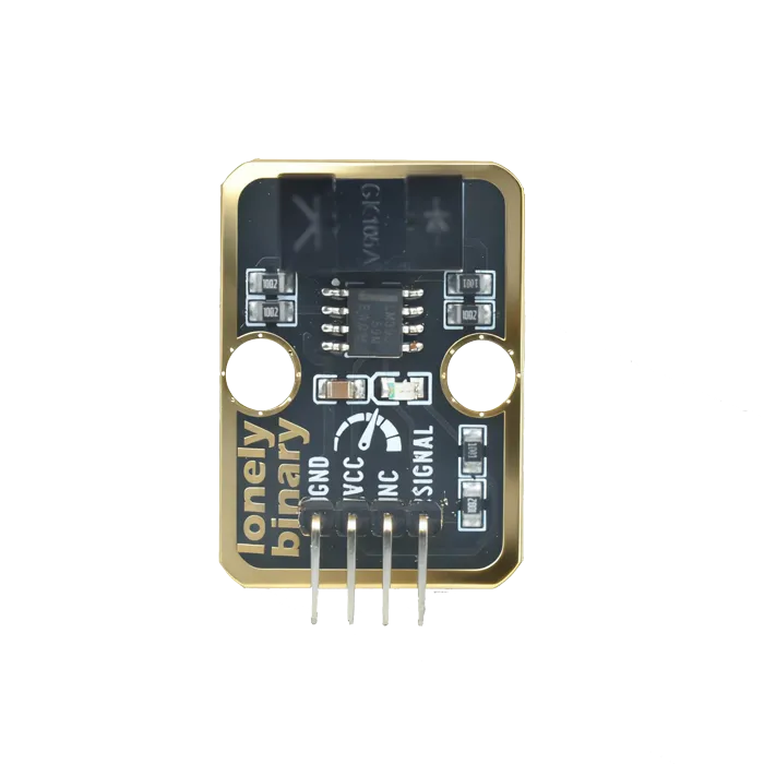
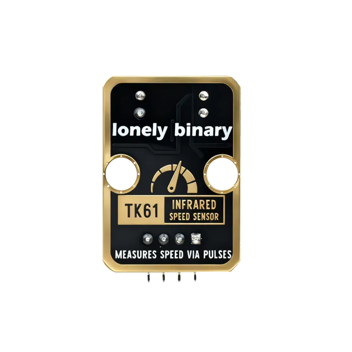
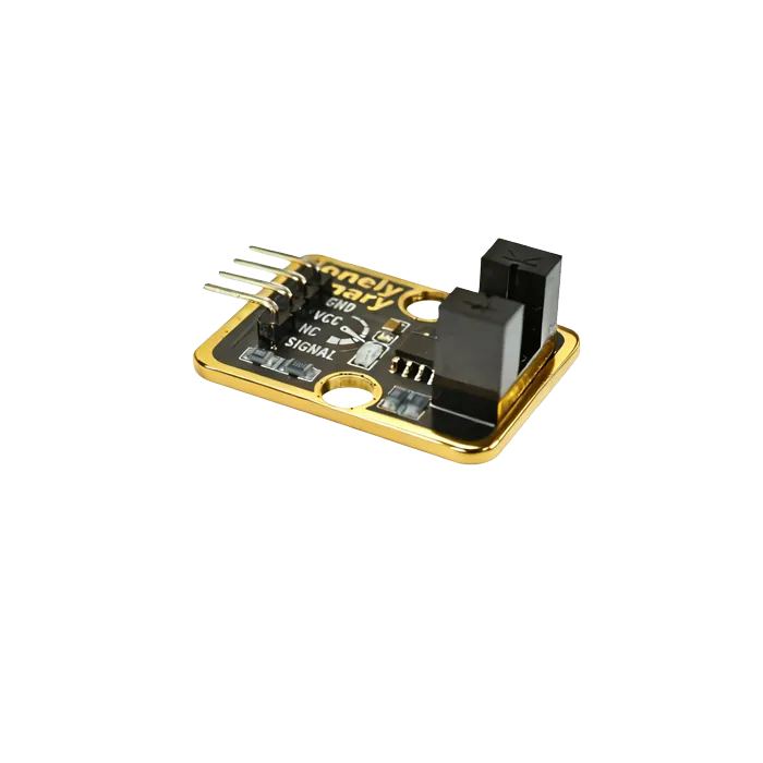
Pinout
- GND (negative): Like the negative terminal (-) of a battery, connect to the control board's GND
- VCC (positive): Like the positive terminal (+) of a battery, connect to the control board's 3.3V or 5V (this module supports both 3.3V and 5V)
- NC (no connection): No actual circuit connection, included for unified interface, can be left unconnected
- SIGNAL (signal output): Detection output pin, connect to the control board's digital pin (e.g. Arduino D2 or Pico GPIO 0)
- Outputs HIGH (HIGH/1) when object blocks light
- Outputs LOW (LOW/0) when no object detected
Wiring
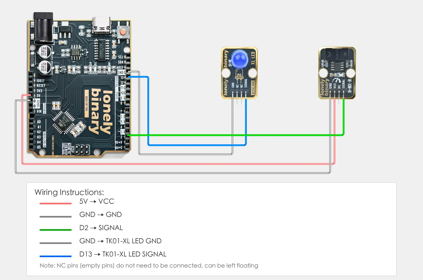
- GND → Control board GND
- VCC → Control board 3.3V or 5V
- SIGNAL → Control board digital pin (use the pin defined in your program)
Example
// Pin number: change this to match your wiring
#define PHOTO_SWITCH_PIN 2  // Arduino digital pin connected to SIGNAL (e.g. D2)
#define LED_PIN 13          // LED pin (Arduino built-in LED on pin 13, or external LED)

void setup() {
  // Initialize pin modes
  pinMode(PHOTO_SWITCH_PIN, INPUT);   // Set photoelectric switch pin as input (to read detection state)
  pinMode(LED_PIN, OUTPUT);           // Set LED pin as output (to control LED on/off)

  // Start serial for debugging (9600 baud)
  Serial.begin(9600);

  Serial.println("Photoelectric switch program started");
  Serial.println("LED on when object blocks light, LED off when no object detected");
}

void loop() {
  // Read photoelectric switch state
  int switchState = digitalRead(PHOTO_SWITCH_PIN);  // Read sensor pin level: HIGH(1)=object detected, LOW(0)=no object

  // Control LED based on detection state
  if (switchState == HIGH) {
    // Object blocks light: LED on
    digitalWrite(LED_PIN, HIGH);
    Serial.println("Object blocks light - LED on");
  } else {
    // No object detected: LED off
    digitalWrite(LED_PIN, LOW);
    Serial.println("No object detected - LED off");
  }

  delay(100);  // Brief delay to avoid reading too fast
}# Import required modules
from machine import Pin # GPIO control
import time # For delay (time.sleep)
# Pin number: change this to match your wiring
PHOTO_SWITCH_PIN = 0 # GPIO connected to SIGNAL (e.g. GPIO 0)
LED_PIN = 1 # LED pin (GPIO 1, or external LED, Pico built-in LED is GPIO 25)
# Create pin objects
photo_switch = Pin(PHOTO_SWITCH_PIN, Pin.IN) # Set photoelectric switch pin as input (to read detection state)
led = Pin(LED_PIN, Pin.OUT) # Set LED pin as output (to control LED on/off)
print("Photoelectric switch program started")
print("LED on when object blocks light, LED off when no object detected")
# Main loop: runs forever
while True:
# Read photoelectric switch state
switch_state = photo_switch.value() # Read sensor pin level: 1=object detected (HIGH), 0=no object (LOW)
# Control LED based on detection state
if switch_state == 1:
# Object blocks light: turn LED on and print message
led.on() # Output HIGH, LED on
print("Object blocks light - LED on")
else:
# No object detected: turn LED off
led.off() # Output LOW, LED off
print("No object detected - LED off")
# Delay 100 milliseconds to avoid reading too fast
time.sleep_ms(100)When it doesn’t work
- The count is low at speed.
- Polling, or too much work in the interrupt handler. Increment a `volatile` counter and nothing else; do the arithmetic in the main loop.
- It counts extra pulses.
- The disc edge is passing slowly through the threshold, so the output hovers. Add hysteresis in software, or spin faster.
- Ambient light affects it.
- It shouldn't much — the beam is enclosed — but strong direct sun into the slot can saturate the detector. Shade it.