Setting the booster
The booster board has an MT3608 switching converter and a 200 kΩ trimmer for each side. It can make anything from about 4.3 V up — and the top of the knob is different on every board, because the trimmer can be a quarter off its marked value. Turn it up with a meter, never to the end stop.
Two converters, two trimmers
The booster has an MT3608 for each side: U1 with its inductor L3 and diode D1 feeds the left rails, and U15 with L4 and D4 the right. The two square parts either side of the socket are the inductors, and the trimmers are the small round parts in the top corners.
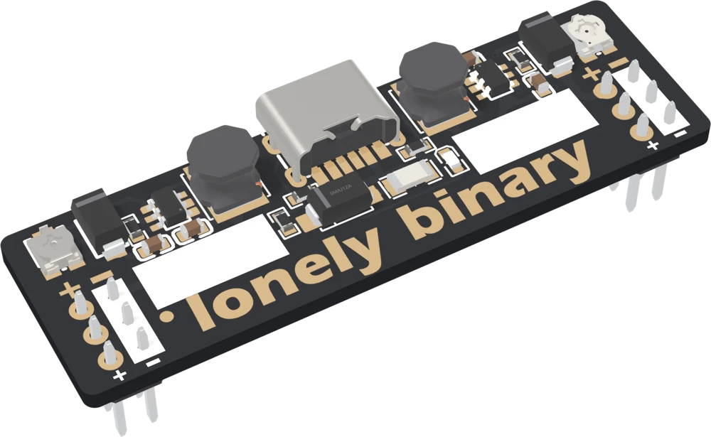
A boost converter makes a higher voltage by switching its inductor to ground and letting go, over and over — 1.2 million times a second here. Each time it lets go, the inductor's stored energy pushes current through the diode into the output at whatever voltage the output is. The chip watches the output through a divider and switches just enough to hold it.
What the trimmer sets
The divider is the trimmer on top and 4.7 kΩ underneath, and the MT3608 holds its FB pin at 0.6 V:
Vout = 0.6 V × (1 + R_trimmer / 4.7 kΩ)About 35 kΩ of trimmer for 5 V, 66 kΩ for 9 V, 89 kΩ for 12 V, 183 kΩ for 24 V. The trimmer is 200 kΩ at full turn — which asks for about 26 V.
Why the top is different on every board
The trimmer is a Bourns TC33, and its resistance is specified to within ± 25 %. So "full turn" is anywhere from 150 to 250 kΩ, and the top of the knob is anywhere from about 20 V to over 32 V. The silkscreen says 28 V, which is the MT3608's rating, not a stop built into the board. On a board with a high trimmer, the end stop is past it.
The bottom has a floor for a different reason. A boost converter cannot lower a voltage. With the trimmer turned down, the chip is asked for less than its input and stops switching, and the input passes through the diode: about 4.3 V.
Setting a voltage
- Nothing wired to the rails. Plug in the cable.
- Meter across that side's + and − pins. It reads about 4.3 V.
- Turn the trimmer a little at a time, and find which way raises it.
- Stop at the voltage you need. Do not turn it to the end.
- Do the other side. Unplug, wire your circuit, plug in, measure again.
The output is always on: each MT3608's enable pin is tied to its supply, so there is nothing to switch off except the cable. Set it first, wire second.
When it does not work
That is the floor of any boost converter: it can raise a voltage but not lower one. With the trimmer turned down, the MT3608 stops switching and the input passes through its diode to the output, less a few tenths of a volt. For lower voltages use the step-down board.
Turn it down now. The MT3608 is rated to 28 V and its switch pin's absolute maximum is 30 V; a trimmer at the high end of its tolerance lets the knob ask for more. Set it to what you need with a meter, and nothing wired to the rail, before connecting anything.
The load wants more power than half an amp at the input can supply at that voltage. At 12 V the booster can give roughly 160 mA in total; a metre of LED strip or a motor wants far more. The fuse trips and the output falls. See the next article for the numbers.
Yes. Each MT3608's enable pin is tied to its supply, so both sides run whenever the cable is in. There is no switch. Set the voltage before you wire anything to the rails, and unplug the cable to change what is wired.
The MT3608 switches its inductor 1.2 million times a second, above hearing, but at very light loads it drops into bursts that can land in the audible range. A faint whine or hiss from the inductor with little connected is normal.
Edit this page — content/books/bbpwd/setting-the-booster.mdx
Questions about this product
See what other owners have asked, and read their solutions.
This page covers several products. Choose yours to see the right discussions.
Discuss this article
Ask about this page. The answer stays here, on the page it belongs to, for whoever hits the same wall next.