Setting the step-down
The step-down board has an AMS1117-ADJ regulator and a 2 kΩ trimmer for each side. The trimmer sets anything from 1.25 V up — but only the first fifth of its travel does anything, because a regulator this kind cannot make more than its input less about a volt.
Two regulators, two trimmers
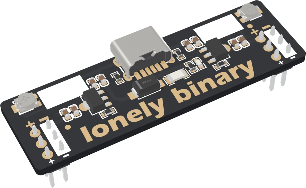
The step-down board has an AMS1117-ADJ for each side: U16 feeds the left rails and U15 the right. Each one has a fixed 220 Ω resistor from its output to its ADJ pin and a 2 kΩ trimmer from ADJ to ground. The trimmers are the two small square parts in the top corners, and a small flat screwdriver turns them.
What the trimmer sets
The AMS1117 holds 1.25 V between its output and its ADJ pin. The 220 Ω carries that 1.25 V, so a fixed current flows through it and on through the trimmer, and the output sits at 1.25 V plus whatever the trimmer drops:
Vout = 1.25 V × (1 + R_trimmer / 220 Ω)With the trimmer at zero that is 1.25 V. At 100 Ω, 1.8 V. At 300 Ω, about 3 V. At its full 2 kΩ the formula asks for over 12 V.
The ceiling
The regulator cannot give out more than it takes in, and it needs some of that for itself: about 1.1 V, from the datasheet, at 0.8 A, a little less at light loads. Its input is the rail after the diode, about 4.6 V. So the most either side makes is about 3.5 V.
That puts the ceiling at roughly 400 Ω of trimmer, a fifth of its travel. Turn past it and the formula keeps asking for more, but the output stays where it is and the regulator has stopped regulating: it is passing its input straight through, less its dropout, including any ripple from the charger.
Setting a voltage
- Plug in the cable with nothing wired to the rails.
- Put a meter across that side's + and − pins.
- Turn the trimmer a few degrees at a time and watch the meter. Find which way is up.
- Stop at the voltage you need. If the meter stops moving before you get there, you are at the ceiling.
- Do the other side, then write both voltages in the white boxes on the board.
- Unplug, wire your circuit, plug in again, and measure once more under load.
The silkscreen on the back says OUTPUT: 1V2-3V8. The bottom is right: 1.25 V is the regulator's own reference. The top is the ceiling on a good day, with a charger at the top of the USB range and almost nothing drawn.
When it does not work
You are probably past the ceiling: the regulator is asked for more than its input less about a volt, so it has stopped regulating and the knob has nothing to act on. Turn the other way until the meter starts to move. If it does not move at either end, check the board has power: the red LED near the middle lights whenever the cable does.
3.8 V needs about 4.9 V at the regulator's input, which means a charger at the top of the USB range and almost no current. With a normal charger and a real load the input is nearer 4.6 V, and the AMS1117 needs about 1.1 V of that for itself. Anywhere from 3.4 to 3.7 V is the real top, depending on the charger and the load.
It should not drift much: the 220 Ω resistor on each side draws about 6 mA on its own, which is above the 5 mA minimum load the datasheet gives as typical (it guarantees regulation from 10 mA). A change of more than a few hundredths of a volt with no load means the trimmer is near the ceiling, where the output is the input less a dropout that changes with current.
That depends on how the trimmer is fitted, and it is quicker to find out than to look up. Put a meter on the rail and turn a few degrees either way. Then remember: small movements, because 1.25 to 3.5 V is packed into the first fifth of a turn.
Every volt the step-down takes off turns into heat, and at hundreds of milliamps that is the limit.
A linear regulator makes heat →Edit this page — content/books/bbpwd/setting-the-step-down.mdx
Questions about this product
See what other owners have asked, and read their solutions.
This page covers several products. Choose yours to see the right discussions.
Discuss this article
Ask about this page. The answer stays here, on the page it belongs to, for whoever hits the same wall next.