
The 0.96 inch board
An 80 × 160 strip on a 29.2 × 25.0 mm board, drawn with a straight header on it. Of the six boards it is the one whose backlight lights when BL is pulled LOW, and the only one whose library entry starts the picture 24 columns into the controller's memory.
What it is for
80 × 160 pixels is 12,800 of them: 25,600 bytes a frame, which at the library's 20 MHz clock is at least 10.2 ms on the wire. The lit area is 10.8 × 21.7 mm, about 0.135 mm a pixel.
That is a strip, not a screen. It suits one reading at a time: a temperature, a state word, a battery bar, in a space where nothing larger fits. Controller in the library's table: ST7735; the panel's own sheet names it ST7735S.
Outline and holes
The board is 29.2 mm along the header edge and 25.0 mm deep, 1.6 mm thick, with four 3.0 mm holes 2.4 mm in from each edge and 24.4 × 20.2 mm apart. The eight header holes are 2.54 mm apart, 17.78 mm across, 2.0 mm from the top edge, and pin 1 (GND) has the square pad.
The model shows a straight header fitted: the mechanical drawing gives 10.14 mm from the board's back face to the top of it, with 1.52 mm of pin tail through on the glass side. The 5 V warning the larger boards print has no room here; the rule is the same.
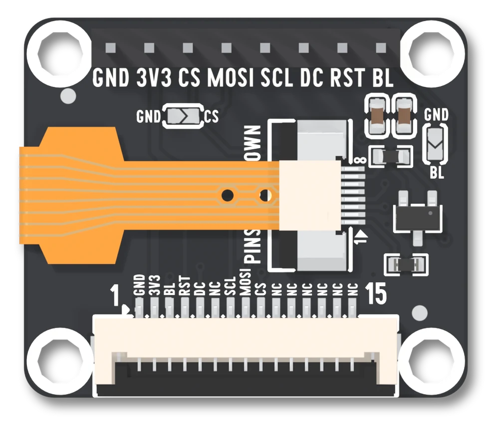
The socket the panel plugs into
The panel's ribbon goes into U32, an 8-way, 0.5 mm socket (FPC-0.5AS-8PWCR-H20). With the header at the top, pin 1 is at the bottom of the socket and pin 8 at the top, as the numbers beside it say. What the board wires to each:
| Pin | Wired to | |
|---|---|---|
| 1 | the lamp's high side | through Q7 and R17 |
| 2 | GND | |
| 3 | RST | |
| 4 | DC | |
| 5 | MOSI | |
| 6 | SCL | |
| 7 | 3V3 | the panel's supply |
| 8 | CS |
The panel's own sheet lists the same eight in the same order, under its own names: LEDA, GND, RESET, RS, SDA, SCL, VDD, CS. There is no separate lamp-return pin, so the lamp comes back to ground through pin 2.
The backlight
Q7, an AO3401 P-channel transistor, sits on the high side: its source is on 3V3, its drain goes through R17 (2.2 Ω) to socket pin 1, and its gate is the BL pad with R18 (10 kΩ) from gate to 3V3. A P-channel part conducts when its gate is pulled below its source, so BL LOW is lit, BL HIGH is dark, and a BL pad nothing drives is dark too, because R18 holds the gate up.
The other five boards are the mirror image, with an N-channel BSS138 on the low
side. The library's entry for LB_TFT_096 is marked active low, so
backlight(255) is full brightness here exactly as it is on them.
Its two jumpers
Both are open as shipped.
GND, silkscreen GND CS, on the left below the header: bridged, CS is tied to GND and the display is always selected. Do not then drive the CS pad, and it must be the only device on that SPI bus.SB3, silkscreen GND BL, at the right edge: bridged, BL is tied to GND, which is on for this board. The lamp is lit whenever there is power and the BL pad is a ground.
There is more on both in the two solder jumpers.
Wiring and the constant
// 3V3 -> 3V3        GND -> GND
// SCL -> GPIO 12    MOSI -> GPIO 11      (classic ESP32: 18, 23)
// DC  -> GPIO 2     RST  -> GPIO 42      (classic ESP32: 2, 4)
// CS  -> GPIO 10    BL   -> GPIO 41      (classic ESP32: 15, 32)
LB_Display display(LB_TFT_096);#include <LonelyBinaryDisplay.h>
LB_Display display(LB_TFT_096); // the only line that changes per panelfrom lb_display import LBDisplay
from lb_panels import TFT_096 # the only line that changes per panel
d = LBDisplay(TFT_096)3.3 V only. The pins are the library's defaults for an ESP32-S3 and a classic ESP32; wiring for your board covers anything else.
What is different about this one
Three things, and the library handles all three if you give it the constant:
- The backlight is active LOW, above.
- The library starts the picture 24 columns in: the controller has more memory than the glass has pixels, and the glass is wired to a window of it.
- The model shows a straight header fitted, the tallest thing on the board at 10.14 mm overall. The other five show holes and no pins in their 3D models.
Everything else is the same circuit as the other five. Where to go next: first light runs the self-test, and when nothing appears is the page for a dark or white screen.
When it does not work
On this board HIGH is off. Q7 is a P-channel transistor on the high side of the lamp, so BL has to go below 3V3 to turn it on, and R18 holds it off while BL is not driven at all. The library knows and inverts backlight(0..255) for LB_TFT_096; a sketch that writes the pin itself has to write LOW for lit.
The glass shows a window of the controller's memory that starts 24 columns in, and a driver that was not told that draws 24 columns to the left of it. The library's entry for this panel carries the offset; TFT_eSPI, Adafruit and hand-written setups usually do not. Use LB_TFT_096 or add the 24 yourself.
SB3 ties the BL pad to GND, which is the lit state on this board. A GPIO that drives BL HIGH is then a short from that pin to GND through the jumper. Unsolder the bridge, or take the BL wire off and leave the pad alone.
At rotation 0 the library reports 80 wide and 160 tall, and the glass lies on the board the other way. A quarter turn, setRotation(1) or setRotation(3), gives the 160 × 80 landscape that matches how it sits; one of the two will read upright with your wiring.
A 1.77 inch glass sold as 1.8, and two different sets of socket facts.
The 1.8 inch board →Edit this page — content/books/lcd/the-0-96-inch-board.mdx
Questions about this product
See what other owners have asked, and read their solutions.
This page covers several products. Choose yours to see the right discussions.
Discuss this article
Ask about this page. The answer stays here, on the page it belongs to, for whoever hits the same wall next.