
The 1.8 inch board
A 128 × 160 picture on a 35.0 × 56.7 mm board. The glass is 1.77 inches, sold as 1.8, and the board's 12-way panel socket is not the 14-pin tail its vendor sheet draws: wire from the board's facts, not the sheet's.
What it is for
128 × 160 pixels is 20,480 of them: 40,960 bytes a frame, which at the library's 20 MHz clock is at least 16.4 ms on the wire. Controller in the library's table: ST7735. The panel's own sheet names none, so that is the library's word and not the vendor's.
It is a handheld size: four or five lines of text, or one small chart. At about 0.22 mm a pixel it has the coarsest pixels of the six.
Outline and holes
The board is 35.0 mm across the header edge and 56.7 mm tall, 1.6 mm thick, with four 4.8 mm holes 24.0 mm apart across and 48.0 mm apart down, 5.5 mm in from the sides. The eight header holes are 2.54 mm apart, 17.78 mm across, with pin 1 (GND) the square one at the left.
The glass module is 33.88 × 43.42 mm and sits on the back, a little over half a millimetre in from either side of the board. The panel's tail comes through a slot 8 mm wide and 6 mm tall.
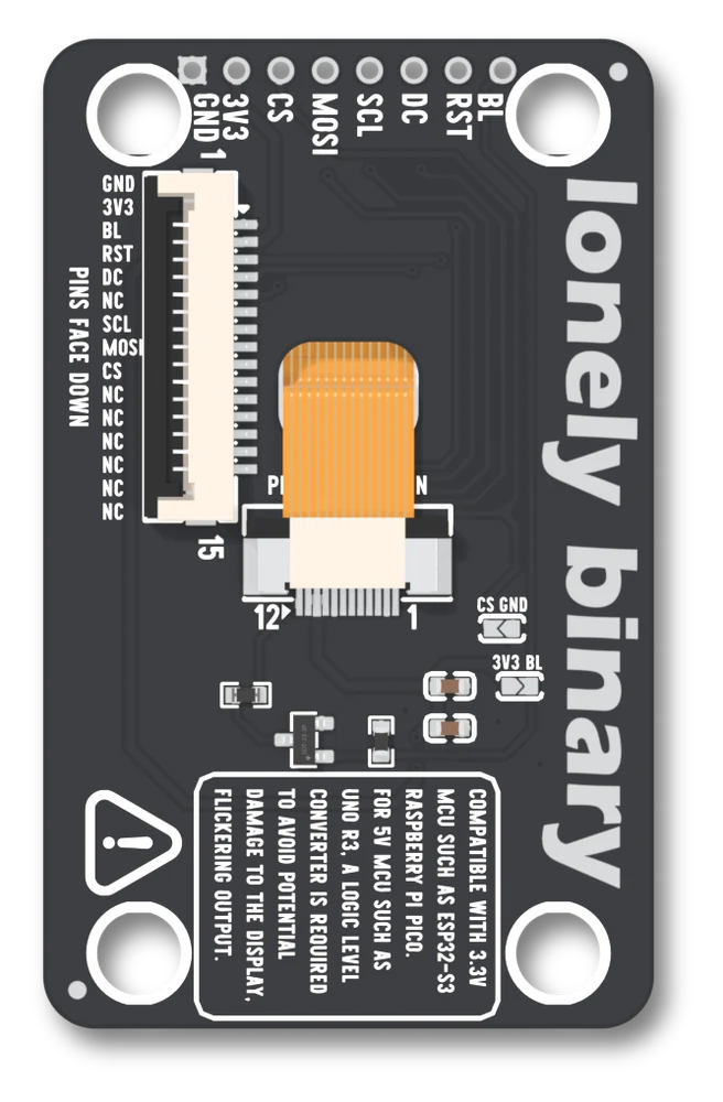
The socket the panel plugs into
The ribbon goes into U7, a 12-way, 0.5 mm socket (FPC-0.5AS-12PWCR-H20). Its pin 1 is at the right-hand end with the header at the top; the silkscreen numbers it 12 to 1 from the left. What the board wires to each pin:
| Pin | Wired to | |
|---|---|---|
| 1 | the lamp's low side | through R6 and Q2 |
| 2, 3, 4 | 3V3 | the one supply rail |
| 5 | GND | |
| 6 | RST | |
| 7 | MOSI | |
| 8 | SCL | |
| 9 | DC | |
| 10 | CS | |
| 11 | GND | |
| 12 | not connected |
That table is what the board does. The vendor's sheet for the glass is a separate document with a 14-contact tail in it, and the two do not agree on how many contacts there are, so this page does not print the sheet's table and does not use it. If you are matching a bare panel to this socket, look at the panel's tail and at the socket's twelve contacts, not at either document.
The backlight
Q2, a BSS138 N-channel transistor, sits on the low side of the lamp: its gate is the BL pad with R2 (10 kΩ) from gate to GND, its drain goes through R6 (2.2 Ω) to socket pin 1, and the lamp's high side is on 3V3. BL HIGH is lit, and a BL pad nothing drives is dark, because R2 holds the gate down.
Its two jumpers
Both are open as shipped.
CS, silkscreen CS GND, on the right, level with the socket's lower end: bridged, CS is tied to GND and the display is always selected. Do not then drive the CS pad.SB3, silkscreen 3V3 BL, just below it: bridged, BL is tied to 3V3, the lamp is lit whenever there is power and the BL pad is a supply. Leave it unconnected; a pin driving it LOW shorts 3V3 to GND.
Both are covered in the two solder jumpers.
Wiring and the constant
// 3V3 -> 3V3        GND -> GND
// SCL -> GPIO 12    MOSI -> GPIO 11      (classic ESP32: 18, 23)
// DC  -> GPIO 2     RST  -> GPIO 42      (classic ESP32: 2, 4)
// CS  -> GPIO 10    BL   -> GPIO 41      (classic ESP32: 15, 32)
LB_Display display(LB_TFT_18);#include <LonelyBinaryDisplay.h>
LB_Display display(LB_TFT_18); // the only line that changes per panelfrom lb_display import LBDisplay
from lb_panels import TFT_18 # the only line that changes per panel
d = LBDisplay(TFT_18)3.3 V only. Wiring for your board has the pins for other chips.
What is different about this one
It is the one whose name is rounded. The part is a 1.77 inch glass, 28.03 × 35.04 mm of picture, and the box and the library both call it 1.8.
And it carries two kinds of fact that the other boards keep apart: the board's own socket, which this page prints, and a sheet for the glass with a different connector in it, which it does not. When they disagree, the board is the one you are holding. Next, first light runs the self-test.
When it does not work
Both are right. The lit area is 28.03 × 35.04 mm, a diagonal of 44.9 mm, which is 1.77 inches; the trade name rounds it up. The library's constant is LB_TFT_18 and nothing in a sketch cares about the difference.
The sheet's table is for a 14-contact tail and the socket fitted on the board, U7, is 12-way, so the two do not map pin for pin. Do not wire to the sheet. What matters is this page's table: what the board does with each of the socket's twelve contacts, taken from its net list.
The library's table marks this panel's colour order as unverified, which the file says in its own words. If red comes out blue and black is still black, it is colour order: one call, and the symptom page names it. It is a panel-table matter, not a wiring one.
The bill of materials lists an 8-pin male header at H2, but the 3D model, its render and the drawing all show the row bare, and what is in your box is not something these files say. The holes are plated through on a 2.54 mm pitch either way, so a breakaway strip fits.
The sharpest of the six: the smallest pixels, on a 14-way socket.
The 2.0 inch board →Edit this page — content/books/lcd/the-1-8-inch-board.mdx
Questions about this product
See what other owners have asked, and read their solutions.
This page covers several products. Choose yours to see the right discussions.
Discuss this article
Ask about this page. The answer stays here, on the page it belongs to, for whoever hits the same wall next.