
The 2.4 inch board
The same 240 × 320 picture as the 2.0 and 2.8, on a 44.0 × 75.0 mm board, 36.7 × 49.0 mm of it lit. It is the only board whose panel socket is 10-way and 1.0 mm, and the board the library's own examples assume.
What it is for
240 × 320 pixels is 76,800 of them: 153,600 bytes a frame, which at the library's 40 MHz clock is at least 30.7 ms on the wire. Controller in the library's table: ST7789. The lit area is 36.72 × 48.96 mm, 0.153 mm a pixel.
It is the one the book starts a beginner on. It reads across a desk, its resolution is what most example code assumes, and a full redraw is short enough that clearing the screen every loop does not look broken yet.
Outline and holes
The board is 44.0 mm across and 75.0 mm tall, 1.6 mm thick, with four 4.8 mm holes 32.0 mm apart across and 64.0 mm down, 6.0 mm in from the sides. The header holes are 2.54 mm apart, 17.78 mm across, pin 1 (GND) at the left.
The glass module is 42.72 × 58.9 mm on the back, nearly the board's width. The tail comes through a slot 22 mm wide and 6 mm tall, the widest of the six.
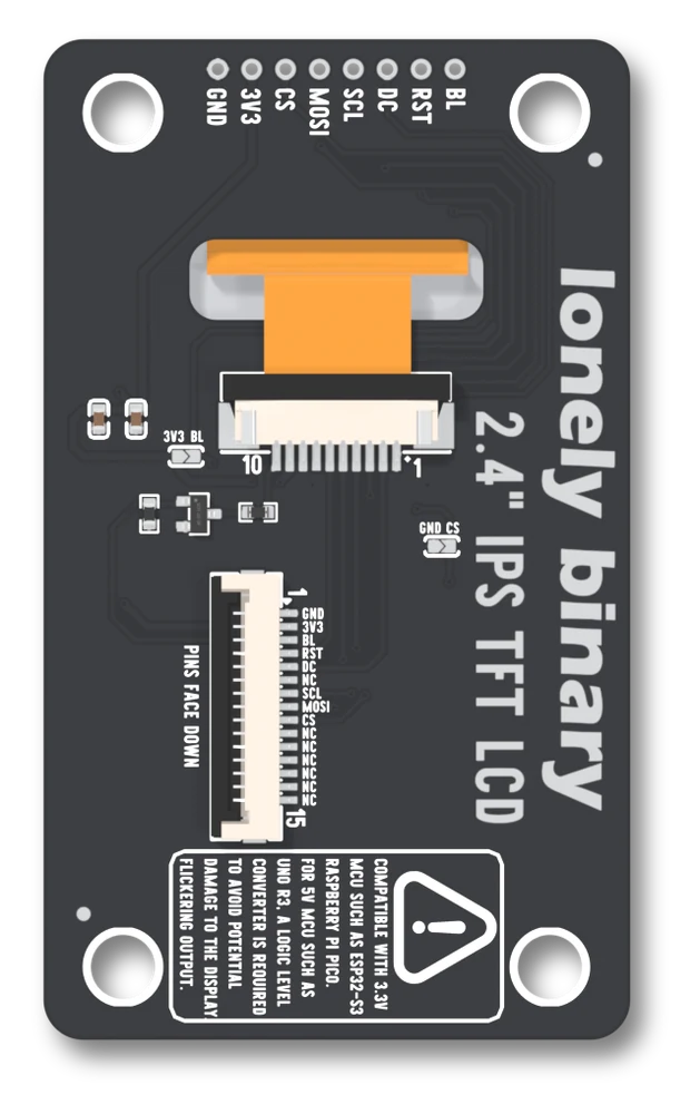
The socket the panel plugs into
The ribbon goes into U32, a 10-way, 1.0 mm socket (FPC-1.0LX-10PH25). It is the only panel socket at that pitch; the other five are 0.5 mm. Pin 1 is at the right-hand end with the header at the top. What the board wires to each:
| Pin | Wired to | |
|---|---|---|
| 1 | GND | |
| 2 | DC | |
| 3 | CS | |
| 4 | SCL | |
| 5 | MOSI | |
| 6 | RST | |
| 7 | 3V3 | |
| 8 | GND | |
| 9 | 3V3 | |
| 10 | the lamp's low side | through R6 and Q2 |
The panel's sheet lists the same ten in the same order, so the two can be read together: its pin 7 is the single supply (this panel has no separate I/O supply) and its pin 9 the lamp's anode.
The backlight
Q2, a BSS138 N-channel transistor, sits on the low side of the lamp: its gate is the BL pad with R2 (10 kΩ) from gate to GND, its drain goes through R6 (2.2 Ω) to socket pin 10, and the lamp's high side is on 3V3. BL HIGH is lit; a BL pad nothing drives is dark.
Its two jumpers
Both are open as shipped.
GND, silkscreen GND CS, on the right, below the socket: bridged, CS is tied to GND and the display is always selected. Do not then drive the CS pad.BL, silkscreen 3V3 BL, on the left, level with the socket's contacts: bridged, BL is tied to 3V3 and the lamp is lit whenever there is power. Leave the BL pad unconnected.
Both are covered in the two solder jumpers.
Wiring and the constant
// 3V3 -> 3V3        GND -> GND
// SCL -> GPIO 12    MOSI -> GPIO 11      (classic ESP32: 18, 23)
// DC  -> GPIO 2     RST  -> GPIO 42      (classic ESP32: 2, 4)
// CS  -> GPIO 10    BL   -> GPIO 41      (classic ESP32: 15, 32)
LB_Display display(LB_TFT_24);#include <LonelyBinaryDisplay.h>
LB_Display display(LB_TFT_24); // the only line that changes per panelfrom lb_display import LBDisplay
from lb_panels import TFT_24 # the only line that changes per panel
d = LBDisplay(TFT_24)3.3 V only. Wiring for your board has the pins for other chips.
What is different about this one
Its panel socket: 10-way, 1.0 mm, one supply pin. Everything the sketch sees is the same as the 2.0 and the 2.8 inch, because the controller and the 240 × 320 are the same; only the glass is a different size, and the pixel with it.
Next, first light runs the self-test.
When it does not work
It is. This panel's tail is 10 contacts at 1.0 mm, about 11 mm across, and the slot in the board is 22 mm wide to take it. The other panels are 0.5 mm. Do not try a panel from one of the others in this socket: the pitch is different.
The right-hand end with the header at the top. The silkscreen numbers it 10 to 1 from the left, and the 15-way socket below it counts from the top. The board prints both, so check the printed number against this page's table before you decide something is swapped.
The electronics did not change and the outline did: 44.0 × 75.0 mm against 36.0 × 64.0, with the four 4.8 mm holes 32.0 × 64.0 mm apart. The sketch needs one constant changed; the enclosure needs a new drawing.
The board prints 2.4 inch IPS TFT LCD, and the panel's drawing says its viewing direction is all. Neither gives an angle in degrees, brightness or contrast, so this page does not either. Look at yours from where it will be mounted.
The same picture on the largest of the three, with a revision printed on it.
The 2.8 inch board →Edit this page — content/books/lcd/the-2-4-inch-board.mdx
Questions about this product
See what other owners have asked, and read their solutions.
This page covers several products. Choose yours to see the right discussions.
Discuss this article
Ask about this page. The answer stays here, on the page it belongs to, for whoever hits the same wall next.