Count 0 to 9 on an Uno
Fourteen wires, one sketch and one line to change depending on which digit came out of the bag. Wire it in three goes — power, control, segments — and check after the first two, because a fault found early is one wire and not fourteen.
What you need
One driver board with its header soldered in, one digit, an Arduino Uno, a breadboard and about fourteen jumper wires. Either kind of digit works; read the part number off the side before you start, because one line of the sketch depends on it.
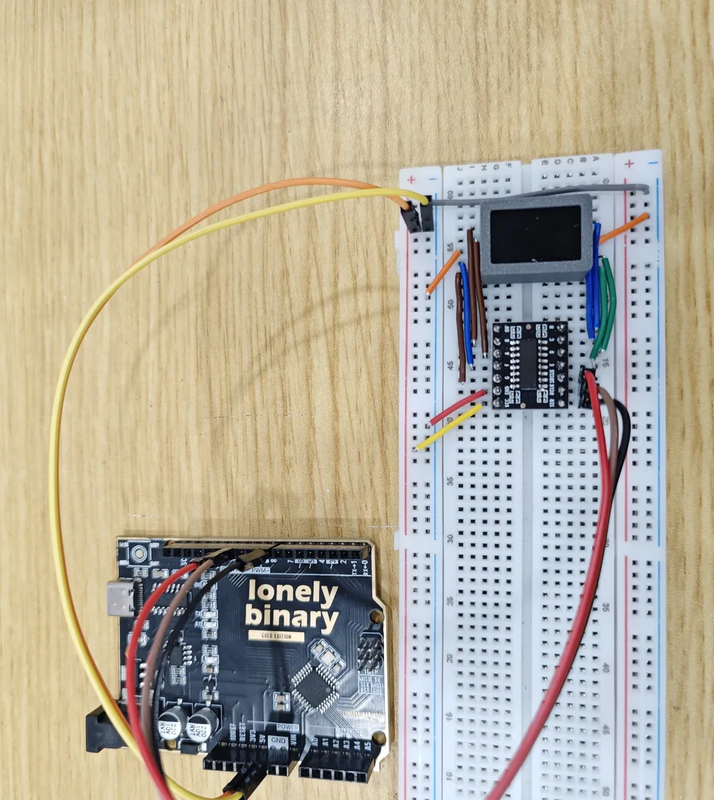
Wire it in three goes
Not because it is difficult, but because checking after each stage turns a fourteen-wire fault into a two-wire one.
Power first. 5 V to VCC, GND to GND. Ground does nothing you can see and is the wire most often left out.
Then the three control wires. D8 to SER, D11 to RCLK, D12 to SRCLK. The pin numbers are the sketch's choice, not the board's — any three spare digital pins work as long as the sketch says the same thing.
Then the eight segments and the common. A to A, through to H. Then both of the digit's common pins to GND if it is a 5161AS, or to 5 V if it is a 5161BS. No jumper should cross another.
Set one line and upload
Open the sketch below, set COMMON_ANODE on the first line to match the part
number on your digit, and upload with Tools → Board → Arduino Uno and the
port that appears when you plug the board in.
It should count 0 to 9, half a second each, and start again.
What it is doing
Three things, each of which has its own page in this book.
It holds a table of ten bytes, one per digit, written so a 1 bit means a lit segment. It flips every byte on the way out if the digit is common anode, in one function rather than in a second table. And it sends each byte with the latch held low, then pulses the latch, so all eight segments change together.
The only line that is specific to your box is the first one.
Make it yours
Three changes worth trying, in rising order of difficulty.
Count the other way. Change the for loop to for (int i = 9; i >= 0; i--).
Hold one character. Put shiftWrite(segOut(kDigits[5])); at the end of
setup(), empty loop(), and the digit shows a 5 until you unplug it.
Show the dot. shiftWrite(segOut(kDigits[3] | 0x80)); shows 3. — bit 7
is the decimal point, and the or happens before the inversion, so it works on
both kinds of digit.
The code
Counts 0 to 9 and starts again, half a second a digit. The only line you should need to change is COMMON_ANODE on the first line: 0 if the side of your digit says 5161AS, 1 if it says 5161BS. If the pin numbers do not suit your board, change the three constants under it and the wiring to match.
// 0.56" seven-segment digit driven by a 74HC595 driver board.
//
// Wiring (Arduino Uno R3):
//   Uno 5V  -> board VCC
//   Uno GND -> board GND
//   Uno D8  -> board SER     (data)
//   Uno D11 -> board RCLK    (latch)
//   Uno D12 -> board SRCLK   (shift clock)
//   board A B C D E F G H -> digit A B C D E F G H   (H is the decimal point)
//   digit's two common pins -> GND on a 5161AS, 5V on a 5161BS
//
// Arduino IDE: Tools > Board > Arduino AVR Boards > Arduino Uno
//              Tools > Port  > the port that appears when the board is plugged in
// No library needed.

#define COMMON_ANODE 0   // 0 = 5161AS (commons to GND), 1 = 5161BS (commons to 5V)

const int PIN_SER   = 8;    // data
const int PIN_RCLK  = 11;   // latch
const int PIN_SRCLK = 12;   // shift clock

const int stepDelayMs = 500;

// Bit 0 is segment A, bit 7 the decimal point. Written for a common-cathode
// digit: a 1 lights its segment.
const uint8_t kDigits[10] = {
  0b00111111, // 0
  0b00000110, // 1
  0b01011011, // 2
  0b01001111, // 3
  0b01100110, // 4
  0b01101101, // 5
  0b01111101, // 6
  0b00000111, // 7
  0b01111111, // 8
  0b01101111, // 9
};

// A common-anode digit lights a segment when its pin goes LOW, so the same
// table goes out inverted. One place, so there is only one table to maintain.
static uint8_t segOut(uint8_t raw) {
#if COMMON_ANODE
  return (uint8_t)~raw;
#else
  return raw;
#endif
}

// Nothing lit. Not the same byte on the two kinds of digit.
static uint8_t blankPattern() {
#if COMMON_ANODE
  return 0xFF;
#else
  return 0x00;
#endif
}

// Hold the outputs still, shift eight bits in, then show them all at once.
static void shiftWrite(uint8_t data) {
  digitalWrite(PIN_RCLK, LOW);
  shiftOut(PIN_SER, PIN_SRCLK, MSBFIRST, data);
  digitalWrite(PIN_RCLK, HIGH);
}

void setup() {
  pinMode(PIN_SER, OUTPUT);
  pinMode(PIN_RCLK, OUTPUT);
  pinMode(PIN_SRCLK, OUTPUT);

  shiftWrite(blankPattern());   // start blank, not with whatever was in the register
}

void loop() {
  for (int i = 0; i <= 9; i++) {
    shiftWrite(segOut(kDigits[i]));
    delay(stepDelayMs);
  }
}
The segment table is written once, for a common-cathode digit, and segOut() flips it on the way out when COMMON_ANODE is 1. That is also why blankPattern() returns 0xFF rather than 0 for a 5161BS: on that part, all bits high is the pattern that lights nothing. setup() sends it so the display starts blank instead of showing whatever the register powered up with.
When it does not work
Check the commons before anything else. A 5161AS wants both of them at GND and a 5161BS wants both at 5 V, and the wrong rail gives you a display that is dark and undamaged. After that, check that the Uno's GND actually reaches the board's GND — a missing ground looks identical.
COMMON_ANODE is set the wrong way for your digit. The blank pattern the sketch sends in setup() is 0x00 for a common-cathode part, and on a common-anode part that lights everything. Read the part number on the side of the digit and set the first line to match.
Same cause, seen in the loop instead of at startup. Every bit is inverted, which is what COMMON_ANODE controls. Change it, upload again, and both the blank pattern and the digits come right together.
One wire. Work out which segment letter is missing, then check that single jumper at the board end and at the digit end. If it is intermittent rather than always missing, it is the header — the boards ship with the pin strips loose, and an unsoldered contact changes every time the bench moves.
That is the Uno, not this display. Unplug it, open Tools > Port, plug it back in and use whichever port appeared. If no port appears at all, it is the cable or the driver, and nothing on the breadboard is involved.
Five faults, told apart by the shape on the glass rather than by guessing.
When nothing lights →Edit this page — content/books/seven-segment/count-zero-to-nine.mdx
Questions about this product
See what other owners have asked, and read their solutions.
24-Pack 0.56" 7-Segment LED with 74HC595 Driver
Loading discussions…
Discuss this article
Ask about this page. The answer stays here, on the page it belongs to, for whoever hits the same wall next.