The driver board
Fourteen pins on a board the size of a postage stamp: two for power, three for your microcontroller, eight for the digit and one for the next board along. Also eight resistors you do not have to buy, and two chip pins the board decides for you.
What is on it
A 74HC595 in a small surface-mount package, eight resistors, and two rows of
seven holes. The chip is marked SM74HC595D — one manufacturer's version of a
part that has been made by everybody since 1982, and every datasheet for it
says the same things about what it does.
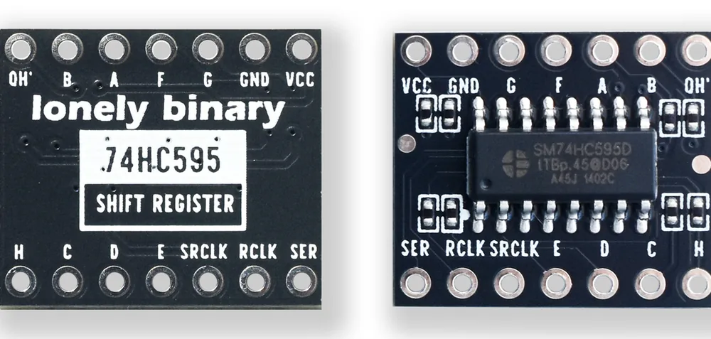
The fourteen pins
Six of them are the chip's own interface and eight are the display. That grouping is worth holding on to, because it is also the order you wire them in: power, then the three control wires, then the eight segments.
The eight output pins are named A to H rather than QA to QH, which is what the chip's datasheet calls them. The board is renaming them after the segments they are meant to drive, and H is the decimal point — the eighth LED in the package, which has no letter of its own on the digit.
The two pins that are not there
A 74HC595 has sixteen pins. Fourteen come out to the headers; the other two are decided on the board and cannot be changed.
OE, output enable, would let you switch all eight outputs off at once without changing what is in the register. Here it is tied on. To blank the display you send a blank byte, which is a slightly different thing — the register loses the digit rather than hiding it.
SRCLR, the shift register's reset, would clear all eight cells in one pulse. Here it is tied inactive. To clear the register you shift eight zeros through it, which costs eight clock pulses and nothing else.
Neither absence matters for a display. Both are worth knowing about the moment you read somebody else's 74HC595 code and find pins your board does not have.
Eight resistors you do not have to buy
An LED wired directly across a supply takes as much current as the supply can give it, and that is bad for both. Each segment needs a resistor in series to limit it, and on a bare digit that means eight through-hole resistors and sixteen extra joints.
They are already here, in the four pairs of small black parts around the chip on the back. That is why the segment pins go straight from the board to the digit with nothing between them.
They are unmarked, so their value cannot be read off them, and it is not published anywhere. If the exact current matters to your project — and it does once you chain several boards — put a meter in series with one segment and find out.
When it does not work
They do — one side is the mirror of the other, because you are looking at the same pins from the back. The side with the chip on it reads VCC GND G F A B QH′ along the top; turn the board over and the same row reads QH′ B A F G GND VCC. Pick a side and stay on it.
The chip has one and the board does not bring it out. OE switches all eight outputs off at once, and on this board it is tied on permanently — so the outputs are always driving, and you blank the display by sending a blank byte instead. The reset pin is handled the same way.
No. There are eight on the back of the board, one in series with each segment output, which is what the listing means by built-in resistors. Adding more in series would only make the digit dimmer. Their value is not printed on them, so if you want to know the current, measure it.
They are meant to be. Solder the strip into the row of holes before using a breadboard — a wire pushed through an unsoldered hole makes a contact whose resistance changes whenever anything moves, and the symptom is segments that flicker or drop out and come back.
Twelve of one and twelve of the other, identical from the front and wired opposite ways.
Two kinds of digit →Edit this page — content/books/seven-segment/the-driver-board.mdx
Questions about this product
See what other owners have asked, and read their solutions.
24-Pack 0.56" 7-Segment LED with 74HC595 Driver
Loading discussions…
Discuss this article
Ask about this page. The answer stays here, on the page it belongs to, for whoever hits the same wall next.