Ten pins and two commons
Five legs on the front of the digit, five on the back, and the middle one of each row is a common. The eight that are left are in the same order as the driver board's eight outputs, which is not a coincidence and means no jumper has to cross another.
Ten legs, and what each one is
Hold the digit with the decimal point at the bottom right. The legs are numbered the way every chip in a two-row package is numbered: from the bottom left, along the bottom, then back along the top from the right.
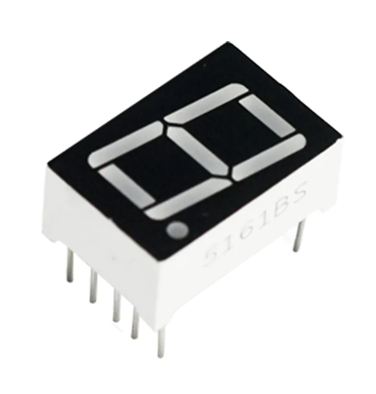
The row nearest you carries E, D, common, C, H from left to right. The row away from you carries G, F, common, A, B. Two commons, one in the middle of each row, and they are the same connection inside the package.
The order is the same on both parts
Look at the driver board's top row: after VCC and GND, its segment outputs read G F A B. Look at its bottom row: after the three control pins, they read E D C H.
Those are the digit's two rows, in the digit's order. Sit the digit above the board's segment pins and every wire runs down its own column or one hole over.
Four of the eight are directly above their own hole and four shift by one. None of them crosses another, on either row, which gives you a check you can do from across the room: if a jumper crosses another jumper, one of them is wrong.
The two that leave
The commons are the only legs that do not go to the driver board. There is no pin on the board for them — the board drives segments, and the common is the return path for all eight of them together.
They go to a rail instead. GND for a 5161AS, 5 V for a 5161BS, the same rail the board's VCC is on. Getting this wrong is the single most common reason a display that is otherwise wired perfectly stays completely dark, and it looks exactly like a missing ground, so check it first.
One wire is enough electrically. Two is better, because every segment's current
comes back through this connection: a digit showing 8. puts eight segments'
worth through it, and a breadboard contact is not a great conductor.
Before the wires, the headers
The driver boards arrive with their pin headers loose in the bag. Solder the strip in before the board goes anywhere near a breadboard.
A wire pushed through an unsoldered hole makes a contact that works when you press it and stops when you let go, and whose resistance changes every time anything on the bench moves. The symptom is a segment that comes and goes, or a digit that is right until you touch the board — which reads as a code bug and is not one. The digits themselves need no soldering; their legs are already there.
When it does not work
Decimal point at the bottom right. That is the only orientation the segment names are written for, and turning the part 180 degrees swaps every pin for the one opposite it — a 2 becomes a 5, a 6 becomes a 9, and nothing looks broken enough to suspect the part is upside down.
Then it is not the part this book is about. Every digit in the 24-pack is a ten-pin package with five legs on each long side at 0.1 inch pitch, which straddles a breadboard's centre channel with one hole to spare each side.
Then one of them is in the wrong hole. On both rows the order on the digit matches the order on the board, so a correct set of eight jumpers never crosses. That makes a crossing the fastest visual check there is — before you start reading pin names, look at the wires.
Look at that one wire first and the breadboard hole under it second. Every segment goes through an identical resistor on the board, so a dim one is extra resistance somewhere in its own path — usually a push-fit contact in an unsoldered header, or a breadboard hole that has been stretched by a thick lead.
Which bit lights which bar, and what changes when the digit is common anode.
One byte, one digit →Edit this page — content/books/seven-segment/ten-pins-and-two-commons.mdx
Questions about this product
See what other owners have asked, and read their solutions.
24-Pack 0.56" 7-Segment LED with 74HC595 Driver
Loading discussions…
Discuss this article
Ask about this page. The answer stays here, on the page it belongs to, for whoever hits the same wall next.