Two kinds of digit
Twelve digits in the box are 5161AS and twelve are 5161BS. They are the same size, the same colour and the same pinout, and one of them lights a segment when the pin goes HIGH while the other lights it when the pin goes LOW. The only place it is written down is the side of the package.
The same part, built backwards
Inside the package, all eight LEDs share one leg. Which leg they share is the whole difference.
On a 5161AS the shared leg is the cathode — the negative end of every segment. Tie it to ground and a segment lights when its own pin is pushed up to 5 V.
On a 5161BS the shared leg is the anode — the positive end. Tie it to 5 V and a segment lights when its own pin is pulled down to 0 V.
Both controls matter. A 5161AS lights on HIGH; a 5161BS lights on LOW. The same output pin doing the same thing produces opposite results on the two parts, and there is no wiring you can do to make them behave the same way.
Where it is written
On the side of the white plastic, moulded in relief below the window:
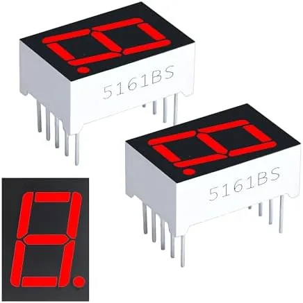
Nothing on the front tells you. The window, the segments and the ten legs are identical, and the two kinds arrive in the same box. Read the side before you wire anything, and keep the two kinds in separate bags once you have.
What it costs in the sketch
Two things, both small, both easy to get wrong once and never again.
Where the commons go. GND on a 5161AS, 5 V on a 5161BS. Two wires.
Whether the byte is inverted. Segment tables are written for a common-cathode part, where a 1 bit means a lit segment. On a common-anode part a lit segment needs a 0, so the same table is sent with every bit flipped. In the sketch that is one operator:
#define COMMON_ANODE 0  // 0 for 5161AS, 1 for 5161BS

static uint8_t segOut(uint8_t raw) {
#if COMMON_ANODE
  return (uint8_t)~raw;   // every bit flipped on the way out
#else
  return raw;
#endif
}
The consequence people miss is blank. Blanking a common-cathode digit means
sending 0x00; blanking a common-anode digit means sending 0xFF. Get that
backwards and the display comes up with every segment lit at power-on, before
the loop has run once, which looks like a much more serious fault than it is.
One byte, one digit shows both bytes side by side for every character.
When it does not work
It is moulded into the white plastic in the same colour as the plastic, usually below the window, and it takes a raking light to see. Tilt it under a lamp. If you still cannot read it, wire the commons to GND and send 0b00000110: a 5161AS shows a 1, a 5161BS shows everything except a 1.
Not for what it can display — both show the same characters at the same brightness. It matters for two wires and one line of code. Pick one kind, use it for the whole project, and set the sketch to match; mixing them on one board means two different segment tables.
Pins 3 and 8 are joined inside the package, so one wire is electrically enough. Wiring both is still worth doing: it halves the current through each wire and each breadboard contact, and on a digit showing 8 that current is the largest in the circuit.
Nothing lights, and nothing is harmed. The common is the anode of all eight LEDs, so holding it at 0 V means no segment can ever have a voltage across it in the right direction. It is the commonest reason a correctly wired display stays dark.
Where each of the digit's ten legs goes, and why none of the eight jumpers has to cross another.
Ten pins and two commons →Edit this page — content/books/seven-segment/two-kinds-of-digit.mdx
Questions about this product
See what other owners have asked, and read their solutions.
24-Pack 0.56" 7-Segment LED with 74HC595 Driver
Loading discussions…
Discuss this article
Ask about this page. The answer stays here, on the page it belongs to, for whoever hits the same wall next.