Specifications
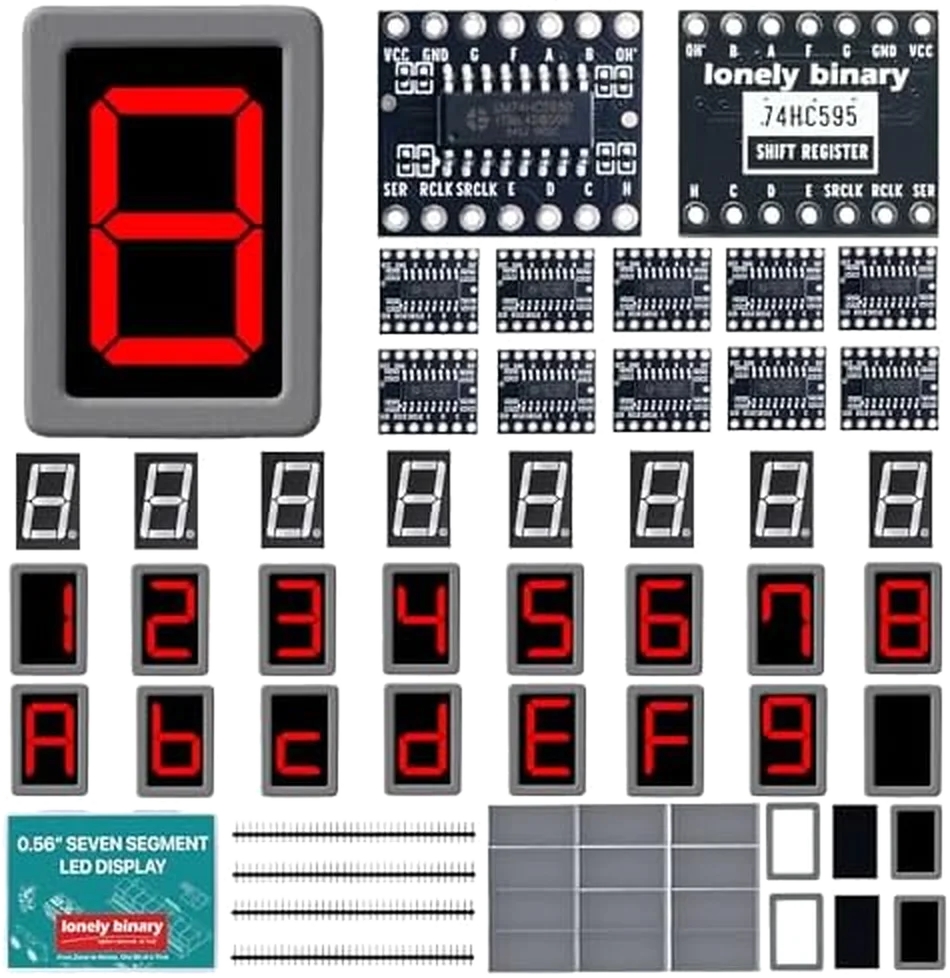
| In the box | 12 × 74HC595 driver boards, 12 × common-cathode digits, 12 × common-anode digits, 24 × snap-on enclosures, and pin header strips |
|---|---|
| Digit | 0.56 inch single character, red, with a decimal point. 5161AS is common cathode, 5161BS is common anode |
| Digit pinout | Ten pins, five each side at 2.54 mm. Nearest row E D com C H, far row G F com A B, decimal point bottom right |
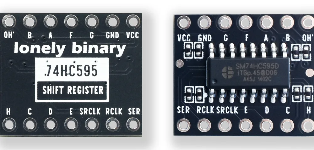
| Driver board | 14 pins: VCC, GND, SER, SRCLK, RCLK, QH′ and eight segment outputs A–H. OE and the reset pin are fixed on the board |
| Series resistors | Eight, one per segment output, already on the back of the board. Unmarked, so the value is not published |
| Supply | 2 to 6 V on VCC. Use the same rail the digit's commons are on — 5 V on an Arduino Uno |
| Output current | 6 mA per output at 5 V as specified, 35 mA absolute maximum, and 70 mA through the whole chip |
| Interface | Three wires: data, shift clock and latch. Chainable through QH′, so more digits still means three wires |
What it does
A seven-segment digit is eight separate LEDs — seven bars and a dot — and each one has its own pin. Wired directly that is eight microcontroller pins and eight resistors for a single character, and sixteen for two.
The small black board in the box removes that. It holds a 74HC595 shift register, which takes a byte one bit at a time on three wires and sets eight output pins from it, and it already carries the eight series resistors. Three wires for one digit, and still three wires for six, because the boards chain.
The two kinds of digit
Twelve of the twenty-four are 5161AS, common cathode. Twelve are 5161BS, common anode. They are the same size, the same colour and the same pinout, and the only place the difference is written is the side of the plastic.
| 5161AS | 5161BS | |
|---|---|---|
| Shared leg | cathode | anode |
| Both commons go to | GND | 5 V |
| A segment lights when its pin is | HIGH | LOW |
| Segment byte | as written | every bit inverted |
| Blank | 0x00 | 0xFF |
Which one you pick up decides two wires and one line of the sketch. Two kinds of digit has the whole of it.
Wiring, in four lines
- 5 V to the board's VCC, GND to its GND.
- Three digital pins to SER, SRCLK and RCLK.
- The board's A to H to the digit's A to H. H is the decimal point.
- The digit's two common pins to GND on a 5161AS, or 5 V on a 5161BS.
The board's segment pins are in the digit's own order — G F A B on one row,
E D C H on the other — so none of the eight jumpers has to cross another. A
crossing wire is a wire in the wrong hole.
What it can and cannot do
One digit shows 0 to 9, A to F and a decimal point: sixteen characters,
because that is as far as seven bars go. There is no K, M, V, W or X.
The limit worth knowing before you build a clock is not per segment, it is per
chip. A 74HC595 may pass 70 mA through its ground pin in total, and a digit
showing 8. lights all eight segments at once. How much
current works it out and says what to
do about it.
Where to start
The handbook below is ten short articles with a working figure in each. If you only read one, read two kinds of digit — it is the question this box turns on. If you have the parts in front of you and want it counting tonight, count 0 to 9 on an Uno is written out wire by wire.
When it doesn’t work
- Which of my digits is which?
- It is moulded into the side of the white plastic, below the window, in the same colour as the plastic — tilt it under a lamp. `5161AS` is common cathode: both common pins go to GND, and a segment lights when its output goes HIGH. `5161BS` is common anode: both common pins go to 5 V, and a segment lights when its output goes LOW. You get twelve of each, and nothing on the front of the part distinguishes them.
- The display shows every segment lit and never changes.
- The sketch's `COMMON_ANODE` setting does not match the part. The blank pattern is `0x00` on a common-cathode digit and `0xFF` on a common-anode one, so a mismatch lights everything at power-on, before the loop has run once. Set it from the part number and both the blank pattern and the digits come right together.
- Nothing lights at all.
- Three things produce exactly this and none of them is a segment wire: the commons not connected, the commons on the wrong rail, or no shared ground between the Arduino and the driver board. Check them in that order. A single broken segment wire costs you one bar, not the whole digit.
- Do I need to add current-limiting resistors?
- No. There are eight on the back of the driver board, one in series with each segment output, so the segment pins go straight to the digit. Their value is not marked and is not published — if the exact current matters, put a meter in series with one segment and measure it.
- Can I drive more than one digit?
- Yes, and it still takes three pins. QH′ on one board goes to SER on the next, and SRCLK and RCLK are shared, so any number of boards behaves as one long shift register. The byte you send first ends up on the board furthest from the Arduino, which is the thing that catches people.
- Do the boards need soldering?
- The pin headers ship loose in the bag, so yes, if you want to use a breadboard. A wire pushed through an unsoldered hole makes a contact whose resistance changes whenever anything moves, and the symptom is segments that drop out and come back — which reads as a code bug and is not one. The digits themselves have their own legs and need nothing.
- Is this the same as a four-digit display module?
- No. A four-digit module lights one digit at a time very fast and depends on code running constantly to keep them all looking lit. Each digit here has its own driver board and holds whatever you last sent it, indefinitely, with the processor doing nothing.