
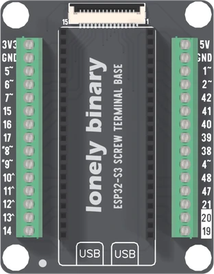
 InteractiveOpen the S3 Screw in 3DTurn the real board over and click any of its 30 holes. Every pad is placed from this design’s own net list.Open in 3D →
Reading this board
The base has no chip of its own. An ESP32-S3 Gold Edition plugs into the two 22-way sockets down the middle, antenna end toward the display connector, and the base brings 26 of its GPIOs out to two 15-way screw terminal blocks, one on each edge at a 3.5 mm pitch. Each GPIO comes out once. There are no pins to solder and no LEDs: each way is the dev board's pin and nothing else.
The silkscreen reads from the display end down, so that is the order here. Open the base in 3D and click either block; the handbook covers using it.
| Way, from the display end | Left block | Right block |
|---|---|---|
| 1 | 3V3 | 5V |
| 2 | GND | GND |
| 3 | GPIO5 | GPIO1 |
| 4 | GPIO6 | GPIO2 |
| 5 | GPIO7 | GPIO42 |
| 6 | GPIO15 | GPIO41 |
| 7 | GPIO16 | GPIO40 |
| 8 | GPIO17 | GPIO39 |
| 9 | GPIO8 | GPIO38 |
| 10 | GPIO9 | GPIO4 |
| 11 | GPIO10 | GPIO48 |
| 12 | GPIO11 | GPIO47 |
| 13 | GPIO12 | GPIO21 |
| 14 | GPIO13 | GPIO20 |
| 15 | GPIO14 | GPIO19 |
GPIO 4 is on the other side
GPIO 4 comes out on the right block, between 38 and 48, although it sits on the dev board's left row. The net list ties the dev board's left-row socket pin 4 to the right block's part pin 6, the tenth way down from the display end. Every other left-row GPIO comes out on the left block. If you wire by row, a sensor on GPIO 4 goes on the wrong side of the board and a sketch that looks for it on the left finds nothing.
What does not come out
GPIO 0, 3, 18, 35, 36, 37, 43, 44, 45 and 46 are not on a terminal, and neither is RST. Their socket positions are connected to nothing. That leaves out the serial pair, the PSRAM lines of an N16R8 module and all four strapping pins (0, 3, 45 and 46).
Power
3V3 is on the left block only and 5V on the right block only, one way each.
Both are the dev board's own pins passed straight through; the base has no
regulator. 5V is whatever the dev board's 5V pin carries, and with USB
as the only supply that is the USB voltage. One GND way is on each block, and
they are the same net, joined with the sockets' ground pins.
The native USB pins are on the right block
GPIO 19 and 20 are the right block's last two ways, and they are the dev board's native USB data pair, D− and D+. A wire to either one shares the USB lines with the computer. Leave them alone unless the sketch is not using native USB. GPIO 48 on the same block is the dev board's RGB LED.
The display connector
A 15-way FPC socket on a 1.0 mm pitch at the top of the board, the same on every ESP32-S3 base. Nothing switches its lines: contacts 3 to 15 are the same nets as terminal ways, so a fitted display owns those GPIOs.
| Contact | Signal | Contact | Signal |
|---|---|---|---|
| 1 | GND | 9 | GPIO10 |
| 2 | 3V3 | 10 | GPIO1 |
| 3 | GPIO41 | 11 | GPIO15 |
| 4 | GPIO42 | 12 | GPIO7 |
| 5 | GPIO2 | 13 | GPIO4 |
| 6 | GPIO13 | 14 | GPIO6 |
| 7 | GPIO12 | 15 | GPIO5 |
| 8 | GPIO11 |
The net list names BL, DC and CS for GPIO41, GPIO2 and GPIO10.
Pins to leave alone
- GPIO15 — ADC2, so analogRead stops working the moment Wi-Fi starts. Unaffected as a digital pin.
- GPIO16 — ADC2, so analogRead stops working the moment Wi-Fi starts. Unaffected as a digital pin.
- GPIO17 — ADC2, so analogRead stops working the moment Wi-Fi starts. Unaffected as a digital pin.
- GPIO11 — ADC2, so analogRead stops working the moment Wi-Fi starts. Unaffected as a digital pin.
- GPIO12 — ADC2, so analogRead stops working the moment Wi-Fi starts. Unaffected as a digital pin.
- GPIO13 — ADC2, so analogRead stops working the moment Wi-Fi starts. Unaffected as a digital pin.
- GPIO14 — ADC2, so analogRead stops working the moment Wi-Fi starts. Unaffected as a digital pin.
- GPIO48 — WS2812B RGB LED, single-wire at 800 kHz. The silkscreen says RGB@IO48.
- GPIO20 — Native USB-C, D+ . Wired straight to the USB-Serial-JTAG peripheral, no bridge chip in the path.
- GPIO19 — Native USB-C, D− . Wired straight to the USB-Serial-JTAG peripheral, no bridge chip in the path.
Every pin
| Pin | Name | Functions | Notes |
|---|---|---|---|
| 3V3 | 3.3 V rail | power | L1. Output of the on-board regulator. Everything on the board runs from it, so budget what the regulator can spare, not what USB can deliver. A steady 3.3 V supply can also power the board through it, but never with USB plugged in at the same time. |
| GND | Ground | power | L2. Ground. Several holes so a breadboard build has one nearby wherever it needs it. |
| GPIO5 | GPIO5 | gpio, adc1, touch | L3 |
| GPIO6 | GPIO6 | gpio, adc1, touch | L4 |
| GPIO7 | GPIO7 | gpio, adc1, touch | L5 |
| GPIO15 | GPIO15 | gpio, adc2 | ADC2, so analogRead stops working the moment Wi-Fi starts. Unaffected as a digital pin. |
| GPIO16 | GPIO16 | gpio, adc2 | ADC2, so analogRead stops working the moment Wi-Fi starts. Unaffected as a digital pin. |
| GPIO17 | GPIO17 | gpio, adc2, uart | ADC2, so analogRead stops working the moment Wi-Fi starts. Unaffected as a digital pin. |
| GPIO8 | GPIO8 | gpio, adc1, touch, i2c | L9. Arduino default: Wire (I²C) SDA. |
| GPIO9 | GPIO9 | gpio, adc1, touch, i2c | L10. Arduino default: Wire (I²C) SCL. |
| GPIO10 | GPIO10 | gpio, adc1, touch, spi | L11. Arduino default: SPI (HSPI) SS. |
| GPIO11 | GPIO11 | gpio, adc2, touch, spi | ADC2, so analogRead stops working the moment Wi-Fi starts. Unaffected as a digital pin. |
| GPIO12 | GPIO12 | gpio, adc2, touch, spi | ADC2, so analogRead stops working the moment Wi-Fi starts. Unaffected as a digital pin. |
| GPIO13 | GPIO13 | gpio, adc2, touch, spi | ADC2, so analogRead stops working the moment Wi-Fi starts. Unaffected as a digital pin. |
| GPIO14 | GPIO14 | gpio, adc2, touch | ADC2, so analogRead stops working the moment Wi-Fi starts. Unaffected as a digital pin. |
| 5V | 5 V rail | power | R1. The USB rail, upstream of the regulator. Feed the board here if you are not using USB, or take 5 V out if you are. |
| GND | Ground | power | R2. Ground. Several holes so a breadboard build has one nearby wherever it needs it. |
| GPIO1 | GPIO1 | gpio, adc1, touch | R3 |
| GPIO2 | GPIO2 | gpio, adc1, touch | R4 |
| GPIO42 | GPIO42 | gpio, jtag | R5 |
| GPIO41 | GPIO41 | gpio, jtag | R6 |
| GPIO40 | GPIO40 | gpio, jtag | R7 |
| GPIO39 | GPIO39 | gpio, jtag | R8 |
| GPIO38 | GPIO38 | gpio | R9 |
| GPIO4 | GPIO4 | gpio, adc1, touch | R10 |
| GPIO48 | GPIO48 | gpio | WS2812B RGB LED, single-wire at 800 kHz. The silkscreen says RGB@IO48. |
| GPIO47 | GPIO47 | gpio | R12 |
| GPIO21 | GPIO21 | gpio | R13 |
| GPIO20 | GPIO20 | gpio, adc2, usb | Native USB-C, D+ . Wired straight to the USB-Serial-JTAG peripheral, no bridge chip in the path. |
| GPIO19 | GPIO19 | gpio, adc2, usb | Native USB-C, D− . Wired straight to the USB-Serial-JTAG peripheral, no bridge chip in the path. |
Edit this page — content/pinouts/s3screw.mdx