Specifications
| Fits | The 44-pin Lonely Binary ESP32-S3 Gold Edition — 22 pins a side, rows 22.86 mm apart. It is in the box |
|---|---|
| GPIOs at the edge | All 36 of the board's header GPIOs, with nothing left out |
| Edge rows | 2 rows of 22 on each side at 2.54 mm: male pins outside, yellow female sockets inside, wired together pin for pin |
| LEDs | 36, one per GPIO, lit while the pin is HIGH. Driven by 6 × SN74HC04 inverters from the 3.3 V rail through 5.1 kΩ, so the pin sees one CMOS input: at most 1 µA and 10 pF |
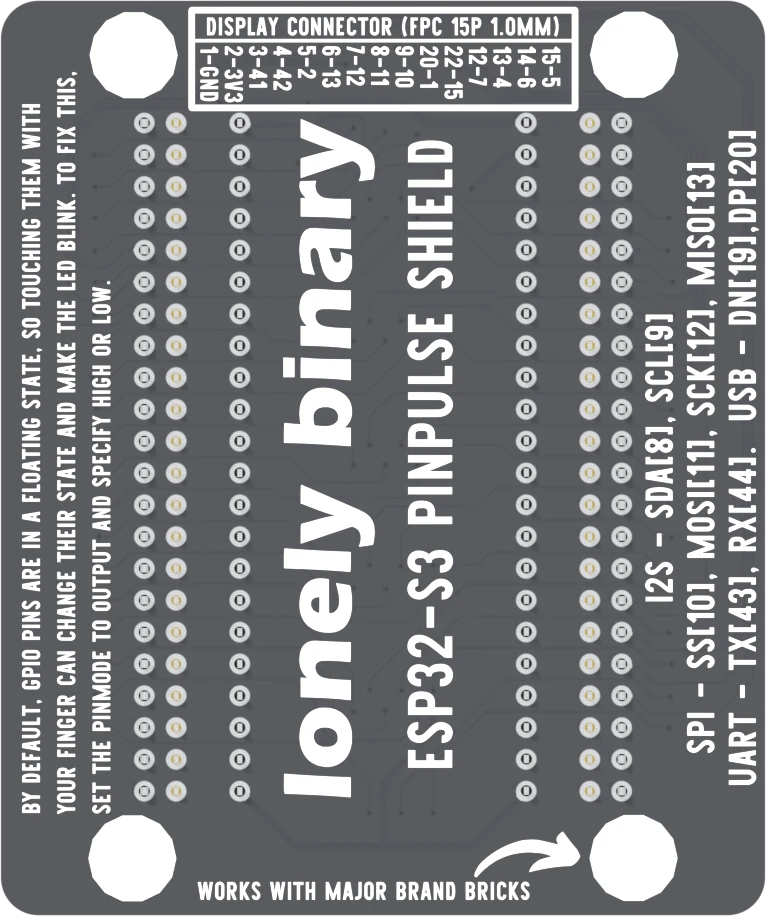
| Display connector | 15-way FPC at 1.0 mm pitch: GND, 3V3 and 13 GPIOs. The legend on the back misprints contacts 10 and 11 as 20 and 22 |
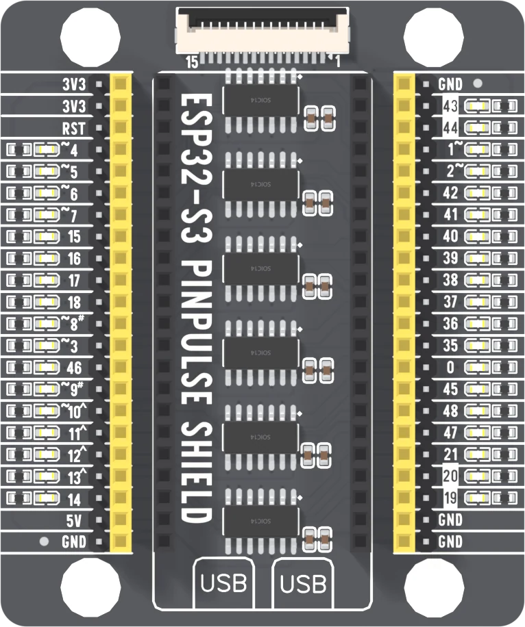
| Power at the edge | 3V3 twice and 5V once on the left, GND once on the left and three times on the right — on both the pins and the sockets. RST at the top of the left edge |
| Spoken for | GPIO 43 and 44 (serial), 19 and 20 (native USB), 35 to 37 (octal PSRAM on N16R8), 0 (BOOT button) and 48 (RGB LED), all on the dev board, not the shield |
| Mounting | 4 × 4.7 mm holes, 40 mm apart across the board |
| Size | 61 × 73 mm, 10.3 mm tall from the underside of the board to the top of the sockets |
What it is
The ESP32-S3 has forty-four pins and nowhere to put them. The PinPulse shield is the board it drops into: two 22-way sockets down the middle, every pin brought back out at each edge twice — as a male pin and as a female socket — and an LED beside every GPIO that lights while the pin is HIGH.
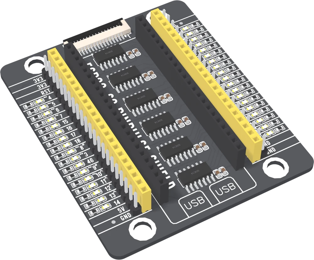
The lights are the reason to own it. "Is this pin doing anything" is answered without a meter, and a serial port, an I²C bus or a display can be watched working. Six SN74HC04 inverter chips sit between the pins and the LEDs, so the pin drives a CMOS input and the light is paid for by the 3.3 V rail.
Wiring, in four lines
- Seat the ESP32-S3 with its two USB sockets over the boxes printed USB. Press straight down, a thumb at each end.
- Plug the USB cable in after the board is seated.
- Take 3.3 V from the top of the left edge and ground from the bottom of either edge, on a pin or a socket.
- For a display, open the latch on the fifteen-way socket, slide the ribbon in, and close the latch.
The two sides of the board
Where to start
The handbook below starts with the one mistake that ends a session — the board in end for end — then the lights, then the pins, and finishes with a sketch that walks a light down every pin it is safe to drive. To see which hole is which GPIO on the board itself, open the shield in 3D.
When it doesn’t work
- Which way round does the ESP32-S3 go?
- USB sockets over the two boxes printed USB at the bottom of the shield, antenna under the display port. The board fits end for end too, and that way its 3.3 V output lands on the shield's ground row — a short across the regulator. Seat the board first, plug the cable in second.
- Why are there pins and sockets on each edge?
- So either end of a jumper fits. The outer row is male pins and the inner yellow row is female sockets, and each socket is wired to the pin beside it — two ways onto the same 22 signals, not 44 different ones.
- Do the LEDs interfere with I²C, SPI or the serial port?
- No, and the six chips are why. Each GPIO drives the input of an SN74HC04 inverter, which TI rates at 1 µA of leakage and 10 pF at most, and the LED's quarter-milliamp comes from the 3.3 V rail through the inverter's output instead of from your pin.
- Some LEDs flicker when I touch the board or wave a hand near it.
- Those pins are floating: nothing in your sketch has set them, so their inverter inputs pick up whatever is in the air. The back of the shield says the same. Set the pin as an OUTPUT and write it HIGH or LOW, or use INPUT_PULLUP, and the flicker stops.
- Some LEDs are lit before I have uploaded anything.
- GPIO 0, 43, 44 and 20 are pulled up inside the ESP32-S3 at reset, so their LEDs light on their own; 43 is also the serial transmit line and flickers when anything prints. GPIO 45 and 46 are pulled down and stay dark. None of that is the shield.
- Which chips drive the LEDs?
- Six 74HC04D hex inverters — SN74HC04 in the board's bill of materials. It is a plain inverter, not the Schmitt-trigger 74HC14, and the difference shows on a floating pin, whose LED can glow half-lit because the HC04 does not snap to one side.
- Which pins does the display port use?
- Contacts 1 and 2 are GND and 3V3; 3 to 15 are GPIO 41, 42, 2, 13, 12, 11, 10, 1, 15, 7, 4, 6 and 5. The table on the back prints contacts 10 and 11 as 20 and 22; the wiring is right and those two numbers are not. Which line a display uses for chip select or backlight is decided by the display module.
- Does 36 lit LEDs overload the board?
- No. Each LED draws about a quarter of a milliamp, so all 36 are around 10 mA from the 3.3 V rail. The ESP32-S3 itself peaks at 340 mA while Wi-Fi transmits, which is the number to budget for.